12x8 Matrix
Graphically create a 12x8 binary matrix to define LED patterns for display
Since R2026a
Libraries:
Simulink Support Package for Arduino Hardware /
Common
Description
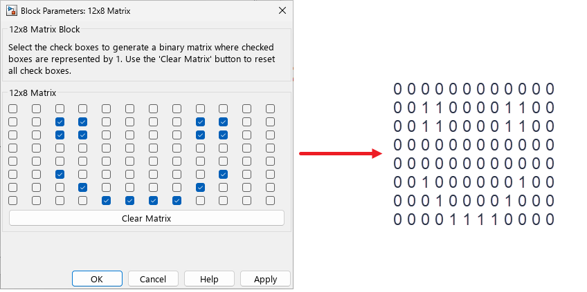
Use the 12x8 Matrix block to provide a graphical interface for specifying LED patterns for Arduino® boards. Double-click the block to use the grid of check boxes arranged in 12 columns and 8 rows, where each check box corresponds to an individual LED on the Arduino board. Select check box to set the corresponding matrix element to 1 (LED ON) and clear the check box to set the element to 0 (LED OFF).
Ports
Output
Parameters
Version History
Introduced in R2026a