Write In-Model Documentation Using Notes
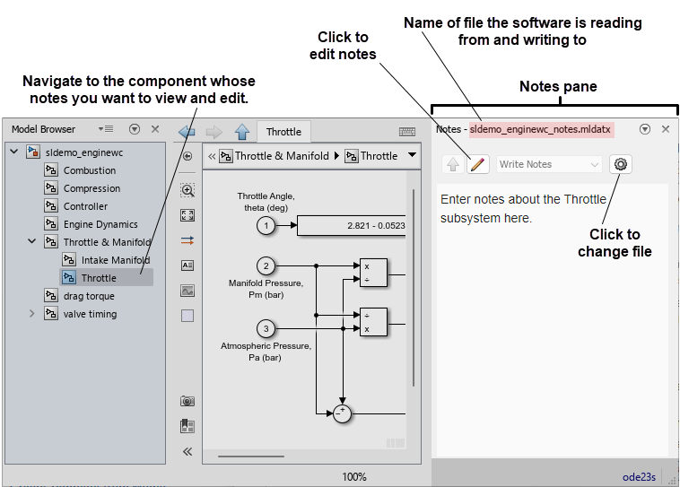
To provide background information or instructions within a model file, you can write notes in the Notes pane of the Simulink® Editor. The notes can include text, images, hyperlinks, equations, and website content. To add labels, short descriptions, images, equations, and hyperlinks to the canvas, use annotations instead. For more information about annotations, see Annotate Models.
To show the Notes pane, in the Simulink Toolstrip, on the Modeling tab, click the arrow on the far right of the Design section. In the Design gallery, under Review, click Model Notes. Alternatively, press Ctrl+Shift+N.
To write notes, you must create a file to store the notes, or load an existing notes file.
Notes are stored in a file with the extension .mldatx. To create a notes
file, in the Notes pane, click the Create a notes file button
![]() . To use an existing notes file, click the Use an existing
notes file button
. To use an existing notes file, click the Use an existing
notes file button ![]() . The notes file is saved separately from the model. If you
move your model to a different folder, the
. The notes file is saved separately from the model. If you
move your model to a different folder, the .mldatx file does not also move,
but the association remains if the file is on the MATLAB® path.
If a model has an associated notes file, the name of the notes file the software is
reading from and writing to is displayed at the top of the Notes pane. If
a model does not have an associated notes file, this message appears at the top of the
Notes pane: This model does not have notes associated with
it. The software can only read from and write to one notes file at a time.
However, you can create multiple notes files for use with the same model, for example, for
users with different roles. The person using the model can load the file pertaining to their
role. Notes files contain the model name and version information to ensure the notes file and
model match.
The notes you can view and edit in the Notes pane are specific to the
component in the model hierarchy you are in, for example, a chart or subsystem. If you
navigate to a different component, you see the notes for that component. For each component in
your model, you can set what the Notes pane displays. To do so, click the
Edit Notes button ![]() . Then, from the drop-down list at the top of the
Notes pane, select one of these options.
. Then, from the drop-down list at the top of the
Notes pane, select one of these options.
Write Notes– Display the notes associated with the component.Use URL for Notes– Enter the URL of a website you want to display.Show Parent Notes– If the component has a parent component, display the notes associated with the parent component.No Notes– Hide the notes.
View Notes and Load Notes Files
You can view notes in the Notes pane.
To view the notes associated with a model component, navigate to the component. For example, to view the notes for a subsystem, enter the subsystem.
To find out which notes file you are viewing the contents of, check the filename at the top of the Notes pane.
To load and view the contents of different notes file, click the Show Options
 button. Click the Use an existing notes file button
 . Select an MLDATX file and click
Open.
. Select an MLDATX file and click
Open.
Add and Edit Notes
Navigate to the component you want to add notes to or whose note you want to edit. For example, to add notes to or edit the notes of a subsystem, enter the subsystem.
Open the Notes pane.
Check whether the model has an associated notes file. If the model has an associated notes file, the name of the notes file the software is reading from and writing to is displayed at the top of the Notes pane. If the model does not have an associated notes file, this message appears at the top of the Notes pane:
This model does not have notes associated with it.If the model has an associated notes file and the Create a notes file
 and Use an existing notes file
buttons are not visible in the
Notes pane, click the Show Options button.
and Use an existing notes file
buttons are not visible in the
Notes pane, click the Show Options button.If the model does not have an associated notes file, or if you want to change the associated notes file, create a new notes file or open an existing notes file.
To create a new file, in the Notes pane, click the Create a notes file button
. Enter a name for the notes file or use the default
name, then click Save. To open an existing file, in the Notes pane, click the Use an existing notes file button
. Select a MLDATX file and click
Open.
Enter edit mode. When you create a new notes file, you automatically enter edit mode. If you open an existing notes file, or if the model already has an associated notes file and you skipped the previous step, click the Edit Notes button
 to enter edit mode.
Add or edit the contents of the note.
To add text, enter the text in the text box.
To inherit the notes from the parent component, in the drop-down list at the top of the Notes pane, select
Show Parent
                  Notes
.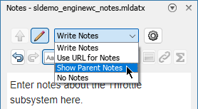
To add images, include hyperlinks, or add equations, use the Image
 , Link
  , and Equation Editor
  buttons, respectively. You can mix text, images,
hyperlinks, and equations in the same note. You can include multiple images,
hyperlinks, and equations in the same note.
buttons, respectively. You can mix text, images,
hyperlinks, and equations in the same note. You can include multiple images,
hyperlinks, and equations in the same note.To use web content as the note, in the drop-down list at the top of the Notes pane, select
Use URL for
                  Notes
. In the text box in the Notes pane title bar, enter the web content URL. Then, press Enter. You can only display the contents of one URL in the note.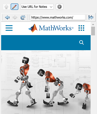
To toggle the notes to read-only mode, click the Read Notes button
 .
.
Note
The notes you add are saved automatically.
Hide and Show Notes
Navigate to the component whose notes you want to hide. For example, to hide the notes of a subsystem, enter the subsystem.
Open the Notes pane.
To enter edit mode, click the Edit Notes button
.To hide the notes of the component you are in, in the drop-down list at the top of the Notes pane, select
No Notes.If the notes of the component you are in are hidden, to show the notes, select
Write Notes.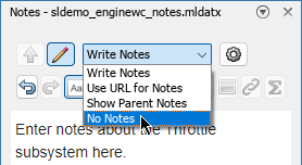
To toggle the notes to read-only mode, click the Read Notes button
.
Related Topics
You can also select a web site from the following list:
Americas
- América Latina (Español)
- Canada (English)
- United States (English)
Europe
- Belgium (English)
- Denmark (English)
- Deutschland (Deutsch)
- España (Español)
- Finland (English)
- France (Français)
- Ireland (English)
- Italia (Italiano)
- Luxembourg (English)
- Netherlands (English)
- Norway (English)
- Österreich (Deutsch)
- Portugal (English)
- Sweden (English)
- Switzerland
- United Kingdom (English)