Model House Heating System
This tutorial shows how to model and simulate a dynamic system using Simulink® software. The model is for a heating system that includes a heater (plant model), controlled by a thermostat (controller model), to heat a room (environment model) to a set temperature. While this is a simple model, the processes for creating model structure and algorithm design are the same processes you will use for more complex models.
Open Completed House System Model
Open the example to access all the model and data files used in this topic.
To open the finalized model, use this command.
open_system("ex_househeat_modeling");

Define a House Heating System
Modeling begins with completion of tasks that are outside of the Simulink software environment. Define model requirements and derive mathematical equations. Collect data for model parameters and output signal data measurements to validate simulation results.

Determine Modeling Goals
Before designing a model, consider your goals and requirements. The goals for modeling the house heating system are:
Observe how the changing outdoor temperature affects the indoor temperature.
Examine the effect of changing parameters on the indoor temperature.
Identify System Components
Once you understand your modeling requirements, you can begin to identify the components of the system.
The house heating system in this tutorial defines a heating system and its relationship to a room. It includes:
Thermal characteristics of a house
Thermal characteristics of a heater
A thermostat to control the heater
Outdoor environment
Indoor environment
The thermostat monitors the room temperature regularly and turns the heater on or off, depending on the difference between the set temperature and the room temperature.

The model for this system includes three components: heater, thermostat, and room.
Define System Equations
Three time-dependent variables define the heat exchange in the room:
Temperature of the room ()
Heat gain: Thermal energy transferred from the heater () to the room
Heat loss: Thermal energy transferred from the room () to the outdoor environment
A differential equation defines the relationship between these variables, but since heat transfer is defined in terms of changing temperature, only room temperature is a state variable.
Rate of Heat Gain Equation
The temperature of the air in the heater is constant at Theater and the room temperature is Troom. Thermal energy gain to the room is by convection of heated air from the heater, with a heat capacity of cair. Heat gain for a mass of air in the heater, , is proportional to the temperature difference between the heater and the room:
The rate of thermal energy gain from the heater is
A fan takes room air, and passes it through the heater and back to the room. A constant amount of air, , flows through the heater per unit time, and replacing with that constant simplifies the equation to
Rate of Heat Loss Equation
Thermal energy loss from the room is by conduction through the walls and windows, and is proportional to the temperature difference between the room temperature and the outside temperature:
The rate of thermal energy loss is
Replacing with where is the thermal resistance simplifies the equation to
Changing Room Temperature Equation
Define the rate of temperature change in the room by subtracting the rate of heat loss from the rate of heat gain:
Collect Parameter Data
Most of the parameter values needed for the house heating model are published in standard property tables. The flow rate for the heater is from a manufacturer data sheet.
List the variables and coefficients from your equations and check for dimensional consistency between the units. Since the unit of time for the model is hours, convert published values for the thermal property of materials from units of seconds to hours.
Equation Variables and Constants. You can use the constant names and values in this table when building the model.
| Equation Variable or Coefficient | Description | Units |
|---|---|---|
| A | Area of wall or window surface | square meter |
| D | Depth of wall or window | meter |
| Q | Thermal energy transferred | joule |
| dQ/dt | Rate of thermal energy transferred | joule/hour |
| k | Thermal conductivity; property of a material to conduct heat
transfer | joule/meter· hour· degree |
| r | Thermal resistivity; property of a material to resist heat transfer
| meter· hour· degree/joule |
| R | Thermal resistance
| hour· degree/joule |
| m | Mass of air in the room or heater The mass of the heater
| kilogram |
| dm/dt | Rate of air mass passing through the heater | kilogram/hour |
| M | Constant rate of air mass passing through the heater
| kilogram/hour |
| c | Specific heat capacity | joule/kilogram· degree |
| Theater | Constant air temperature from heater | degree Celsius |
| Troom | Initial air temperature of room | degree Celsius |
Model House Heating System
Model the top-level structure with components that including interfaces for passing data between individual components. Your model should be organized into a hierarchical structure that corresponds to the components of the system.

Model Top-Level Structure
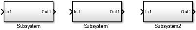
At the top level of the house heating model, use Subsystem blocks to organize your model and create the structure. The model includes the subsystems Thermostat, Heater, and Room.
Open a new Simulink model: Open New Model.
Open the Library Browser: Open Simulink Library Browser
Add Subsystem blocks. Drag three Subsystem blocks from the Ports & Subsystems library to the new model in the Simulink Editor.
Open a Subsystem block. Double-click the block.

Each new Subsystem block contains one Inport (In1) and one Outport (Out1) block. These blocks define the signal interface with the next higher level in a model hierarchy.
Each Inport block creates an input port on the Subsystem block, and each Outport block creates an output port. Add more blocks for additional input and output signals.
On the Simulink Toolstrip, click the Navigate Up To Parent button
 to return to the top level. Rename the
Subsystem blocks as shown. Double-click a block name and type the new
name.
to return to the top level. Rename the
Subsystem blocks as shown. Double-click a block name and type the new
name. 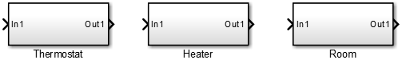
For each component, model the equations, define parameters, prepare the subsystem for simulation, and simulate to verify its behavior.
Model Heater Component
Let’s start by modeling the heater system component. The heater model:
Takes the current temperature from the room and a control signal from the thermostat as inputs
Calculates the heat gain from the heater
Outputs the heat gain when the control signal is on
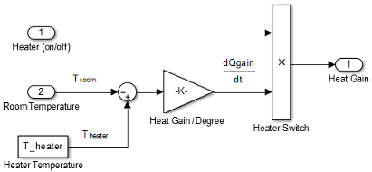
To model the heater subsystem, model the rate of heat gain equation with Simulink blocks:
Subtract Room Air Temperature from Heater Air Temperature. The temperature difference is the current room temperature subtracted from the
constant temperature of the heater
(T_heater).
Open the Heater subsystem.
Click the model and type Sum to display a list of blocks with Sum in the name. Click the Sum block on the list. When prompted for a list of signs, type
|-+to place - and + input ports on the block, and press Enter.The vertical bar (
|) changes the position of input ports by inserting spaces between the ports. A vertical bar at the beginning of the sign list, places a space at the top of the block and shifts the ports counter clockwise.Add a Constant block to model the constant air temperature from the heater. Set the block Constant value parameter to
T_heater. You will define the value ofT_heaterin the Model Workspace.If the block displays
-C-, resize the block to display the variable name.Add a second Inport block to take the room temperature signal from another part of your model.
Add a Gain block to the Heater subsystem. Set the Gain parameter to
M_heater_air*c_air. You will define the values of these variables in the Model Workspace.Connect the output of the Sum block to the input of the Gain block.
Add labels to the signal lines to help trace model components to the equations and model requirements. Double-click above a signal line and enter a label.

Rename the blocks and connect them as shown in the figure.

Model a Heater Switch. The thermostat sends an on/off signal equal to 1 (on) or 0 (off) to the heater. Because the input signal is binary, you can use a Product block to model a switch.
Remove the connection between the In1 and Out1 blocks. Select the line and press Delete.
Add a Product block. Resize the block vertically to align the block in your diagram. Connect the In1 block to the first block input and the block output to the Out1 block. Rename the blocks as shown.

Connect the output from the Gain block to the second input. Move all the connected blocks together. Draw a selection box around the blocks you want to move, and then drag them to the new location.
Rename blocks and add labels to signals as shown in the figure.
The Inport and Outport blocks create ports that connect this subsystem to other subsystems in your model.
Define Heater Model Parameters. You can define parameters in the MATLAB® Workspace and then enter their names in the block parameter dialog boxes. However, a more robust method is to use the Simulink Model Workspace because variable values are saved with the model.
In the Simulink Editor, on the Modeling tab, under Design, click Model Workspace.
In Model Explorer, select Add > MATLAB Variable. In the middle pane, click the new variable
Varand enter the variable name for a block parameter. For this example, enterT_heater.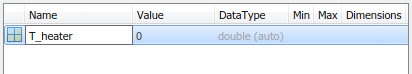
Click the
0value and enter the value for this variable. For this example, enter50degrees.
Using the same approach, add the variable
M_heater_airwith a value of3600kilogram/hour andc_airwith a value of1005.4joule/kilogram· degree.
Prepare Heater Model for Simulation. Set up the heater model for simulation. Think about the expected behavior and how you can test that behavior with a simulation. When the thermostat output is 1 (on), and assuming constant room temperature of 25, the expected output from the gain is (50 – 25) x 3600 × 1005.3 = 9.05 × 10⁷. Verify this output by running the model with these inputs:
Heater on/off signal that changes from
0to1after the 4th hourRoom temperature constant at
25
From the Heater subsystem, click the Navigate Up To Parent button
to navigate to the top level of your model. You can
resize the Heater block as shown in the figure.
Notice the Heater block has a second input port and that each port corresponds to an Inport block or Outport block in the subsystem.
Add a Constant block to represent the room temperature, and set the value to
25(degrees Celsius). Add a Step block for a temporary Heater (on/off) signal. Set Step time to4.Add a Scope block and connect it to the Heat Gain output.

Simulate Heater Model and Evaluate Results. Use the default simulation settings to validate your model design.
Double-click the Scope block to open it.
Simulate the model. Click the Run button
 .
.As the simulation runs, the Scope plots the results.
View the scope trace.

Determine if this result is what you expected.
When the heater on/off signal flips from 0 to 1 at 4 hours, the heater outputs 9.05 × 10⁷ joule/hour. The simulation validates the expected behavior.
Remove Constant, Step, and Scope blocks you added for testing the Heater component.
Model Thermostat Component
You can model a thermostat without using system equations. Requirements for this component:
When the room temperature is below the set temperature, heater is on and the control signal equals 1. When the room temperature is above the set temperature, the control signal equals 0.
To avoid repeated switching around the set temperature, the thermostat allows a hysteresis of 2 degrees Celsius around the temperature set point. If the thermostat is on, the room temperature must increase 2 degrees above the set temperature before turning off. If the thermostat is off, the room temperature must drop 2 degrees below the set temperature before turning on.
This component models the operation of a thermostat, determining when the heating system is on or off. It contains only one Relay block but logically represents the thermostat in the model.
Subtract Set Room Temperature from Room Temperature. If the set room temperature is warmer than the room temperature, the thermostat model sends an “on” signal to the heater model. To determine if this is the case, begin by subtracting the room temperature from the set temperature.
Open the Thermostat subsystem. Add a Sum block. Set the parameter List of signs to
|+-.Connect the Inport block to the + input of the Sum block. The Inport block sets the room temperature.
Add a second Inport block and connect it to the – input of the Sum block. This second Inport block is the current room temperature from the room subsystem. Move the output port to the top of the block. Select the block. In the toolstrip, on the Format tab, select Rotate 90 counterclockwise
 . If you want, you can reshape the block as shown in
the figure by dragging the handles.
. If you want, you can reshape the block as shown in
the figure by dragging the handles.Rename the blocks as shown.

Model Thermostat Signal. Model the signal from the thermostat with a hysteresis value of 2 degrees Celsius.
In the Thermostat subsystem, add a Relay block. Set the Switch on point parameter to
2, and the Switch off point parameter to-2.Connect and rename the blocks as shown in the figure.

Prepare Thermostat Model for Simulation. Prepare the Thermostat subsystem for simulation. Think about the expected behavior of the thermostat and how you can test that behavior with a simulation. When the room temperature rises above the thermostat setting by 2 degrees, the thermostat output is 0. When the room temperature moves below the thermostat setting by 2 degrees, the thermostat output is 1.
From the Thermostat subsystem, click the Navigate Up To Parent button
to navigate to the top level of your model. Resize
the Thermostat block as shown in the
figure.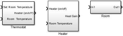
Notice the Thermostat subsystem now has a second input port. Each input port corresponds to an Inport block in the subsystem.
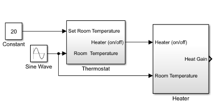
Add a Constant block for the set temperature. Set the Constant parameter to
25(degrees Celsius).Add a Sine Wave block to represent the changing room temperature. Set the Amplitude parameter to
10, the Bias to20, and the Frequency to0.5. These parameters give a variation above and below the temperature set point of 25.Create and connect Scope Viewer at the Heater port.
Connect the two input signals to the Scope Viewer.

Simulate Thermostat Model and Evaluate Results. Use the default simulation settings to validate your model design.
Simulate the model. As the simulation runs, the Scope Viewer plots the results.
Open the Scope to view the scope trace.

Determine if this result is what you expected.
Initially the room temperature is below the set temperature and the relay is on. When the room temperature reaches the set temperature, the relay continues to be on until the room temperature increases by 2 more degrees. Simulation validates the expected behavior.
Model Room Component
Inputs to the room component are heat flow from the heater component and the external air temperature. The room component uses these inputs to compute heat loss through the walls, heat loss through the windows, and the current room temperature.
To design the room subsystem, use the Rate of Heat Loss equation and the Changing Room Temperature Equation.
Model Changing Room Temperature. The rate of temperature change in the room (dTroom/dt) is defined by the equation
The term dQgain/dt is a signal from the Heater subsystem.
Open the Room subsystem block. In the Room subsystem, add a Sum block. Set the List of signs parameter to
|+–.Connect In1 to the + input. The input is the heat gain (
dQgain/dt) from the heater component. The – input connects to the heat loss (dQloss/dt) from the room.Add a Gain block. Set the Gain parameter to
1/(m_room_air*c_air). Connect the output of the Sum block to the input of the Gain block. Label signals as shown in the figure. Dotted signal lines are signals you will connect later.
Model Room Temperature. The output of the Gain block is the change in room temperature
(dTroom/dt). To get the current room temperature
(Troom), integrate the signal.
Add an Integrator block. Set the Initial condition parameter to
Troom_IC.Connect the output of the Integrator block to Out1 as shown.

Model Heat Loss Through Walls and Windows. This equation is the rate of thermal energy loss through the walls and windows:
In the Room subsystem, add a Sum block. Set the List of signs parameter to
|+–. Select the block. In the toolstrip, on the Format tab, click Flip left-right .
.Connect
Troomto the Sum block. Click the signal line forTroomand the + input on the Sum block.Add another Inport block and connect it to the – input of the Sum block. Rename it to Outside Temperature.
Add another Gain block. Set the Gain parameter to
1/R_equivalent. Select the block. In the toolstrip, on the Format tab, click Flip left-right.Connect the blocks as shown in the figure.

Define Room Model Parameters. You can define parameters in the MATLAB Workspace and then enter their names in the block parameter dialog boxes. However, a more robust method is to use the Simulink Model Workspace, which saves parameter values with the model.
In the Simulink Editor, on the Modeling tab, under Design, click Model Workspace.
In the Model Explorer, select Add > MATLAB Variable.
In the middle pane, click the new variable
Varand enter the namem_room_air. In the right pane, enter the value1470(kilograms).Add the variables
T_roomIC=20(degrees Celsius) andR_equivalent=4.329e-7(hour· degree/joule).
Prepare Room Model for Simulation. Prepare the Room subsystem for simulation. Think about the expected behavior and how you can test that behavior with a simulation. When the heater is off (Heat Gain = 0) and the initial temperature of the room (20) is above the outside temperature (10), heat loss should continue until the room temperature is equal to the outside temperature.
From the Room subsystem, click the Navigate Up To Parent button
to navigate to the top level of your model. Resize
the Room block as shown in the
figure.
The Room block now has a second input port. Each input port corresponds to an Inport block in the subsystem.
Add a Constant block and connect it to the Heat Gain input. Set the Constant value parameter to
0(degrees Celsius) to mean that the heater is turned off.Add another Constant block and connect it to the Outside Temperature input. Set the Constant value parameter to
10(degrees Celsius).Add and connect a Scope block to view the changing room temperature.

Simulate Room Model and Evaluate Results
In the toolstrip, set the Stop Time to
20.Simulate the model.
Open the Scope and click the Autoscale button
 to view the scope trace.
Determine if this result is what you expected.
The room temperature starts at the initial room temperature set in the Integrator block. Because the heat gain is 0, the signal decays to the outside temperature (10). The simulation validates the expected behavior.
Prepare Room Model for Second Simulation. Set the constant outside temperature to a value above the initial room temperature (20).
In the Constant block that is connected to the Outside Temperature
input, set Constant value to 30 (degrees
Celsius).

Simulate Model and Evaluate Results
Simulate the model.
Open the Scope and click the Autoscale button
 to view the scope trace.
Determine if this result is what you expected.
Room temperature starts at the initially set temperature of 20, but with the heater off (heat gain = 0) the room temperature rises to the outside temperature — a behavior that the model did not explicitly specify, and might be considered unexpected.
The equation that models the heat loss also models the heat gain when the outside temperature is above the inside room temperature. While the model did not explicitly specify this behavior when the heater is turned off, the result makes sense physically.
Integrate a House Heating Model
Connect model components, add realistic input, and then simulate the model behavior over time to validate the model design.

Integrate Heater and Thermostat Components
To simulate the heater and thermostat subsystems without the Room subsystem, you need a signal for the changing room temperature. Use a Constant block to set the thermostat temperature and a Sine Wave block for a realistic outside temperature signal.
Prepare Model for Simulation
Open your model with the completed subsystems. Remove any blocks you added to test the separate components.
Open the Room subsystem. Double-click the Inport block labeled Heat Gain. In the Inport block dialog box, set Port number to
2. The Heat Gain port moves to the bottom of the Room subsystem.
Connect the Heater (on/off) signal from the Thermostat subsystem output to the Heater subsystem input.
Add a Constant block to set the thermostat room temperature. Set Constant value to
20(degrees Celsius).Add a Sine Wave block to represent the changing room temperature. Set the parameters Amplitude to 10 (degrees Celsius), Bias to
15, and Frequency to0.5.Connect the blocks as shown in the figure.
Add a Scope viewer and add the output signals from Heater, Constant, and Sine Wave blocks.
On the Scope viewer window, in the Configuration Properties button
 click the arrow and then click
Layout icon
click the arrow and then click
Layout icon  . Select two boxes. A second empty graph appears
below the first.
. Select two boxes. A second empty graph appears
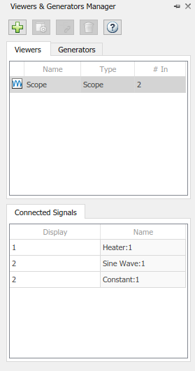
below the first.In the Simulation tab under Prepare, select Viewers Manager.
From the Viewers and Generators Manager, select the Scope. Under Connected Signals, in the rows for Constant and Sine Wave, select the Display entry and change the Display to 2.
Simulate Model and Evaluate Results. Simulate the model using the default stop time of 10.
Simulate the model.
Open the Scope Viewer and view the simulation results. The top graph is the heater gain while the lower graph shows the changing room temperature modeled with a sine wave.

Determine if this result is what you expected.
From about 0 to 1.5 hours, the heater is turned on. Heat gain is not constant but changes because heat gain is a function of the difference between the heater air temperature and the room air temperature. From 1.5 to 5.6 hours, the heater is turned off and the heat gain (top graph) is zero. The simulation confirms the expected behavior.
Integrate Room Component
To simulate the Heater and Thermostat subsystems with the Room subsystem, you need a signal for the changing outside temperature. Simulating the model allows you to observe how the thermostat setting and outdoor temperature affect the indoor temperature.
Prepare Model for Simulation
Open your model with completed subsystems. Remove any blocks you added to test the separate components.
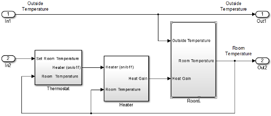
Connect the subsystems as shown.

Add a Constant block for setting the room temperature. Set Constant value parameter to
20(degrees Celsius).Add a Sine Wave block to represent the changing outside temperature. Set Amplitude to
5, Bias to12, Frequency to2*pi/24, and Phase to180.
Add a Scope Viewer block to view simulation results.
In the Signal Viewer, click the Signal Selector button
 . In the Signal Selector dialog box and in the left
pane, select the top model hierarchy. In the right pane, select the Room and Sine
Wave signals.
. In the Signal Selector dialog box and in the left
pane, select the top model hierarchy. In the right pane, select the Room and Sine
Wave signals.
Simulate Model and Evaluate Results
Set the simulation stop time to
24(hours) to represent a day.Simulate the model.
Open the Scope Viewer and view results.

Determine if the simulation result matches your expectation.
When the outside temperature is below the set room temperature, the room temperature fluctuates 2 degrees above and below the set temperature. Since the thermostat subsystem includes a 2 degree hysteresis, this simulation result is expected.
You can compare your results with an example model. In the MATLAB Command Window, enter the command below.
open_system('ex_househeat_modeling_prepared')
Refine Model Parameters. With Simulink models, you can interactively change model parameters and then observe changes in the behavior of your model. This approach allows you to evaluate your model quickly and validate your design.
Change the outside temperature in the Sine Wave block so that upper values are above the set temperature.
In the Sine Wave dialog box, set Amplitude to
5and Bias to19. These settings show what happens when outside temperature is higher than inside temperature.Simulate the model and view the results.

Determine if the results match your expectations.
When the outside temperature is above the set temperature, the room temperature follows the outside temperature with a slight delay. In this case, heat loss works in the reverse direction - and represents the loss of heat from the outside environment into the room.
Model External Interface
Model the external interface for further testing and possible use in a larger model. In Simulink, you model the external interface using Inport and Outport blocks.
Add Inport blocks to read data from the outside temperature and thermostat set temperature into your model.
Add Outport blocks to connect the outside temperature and room temperature to a larger model or to visualize results.
Specify Physical Units
By specifying physical units for model signals, you ensure the consistency of calculations across model components. In Simulink, you specify signal units through Inport and Outport blocks.
Double-click the
In1block to open the Block Parameters dialog box. Select the Signal Attributes tab.In the Unit box, start typing
degree. From the list of symbols and names, select°C degree_Celsius.For the remaining temperature Inport and Outport blocks, set the Unit parameter to
°C degree_Celsius.Display units on block ports. On the Debug tab, select Information Overlays > Units.
Double-click the Heater Subsystem block. Double-click the Heat Gain Outport block to open the Block Parameters dialog box. Select the Signal Attributes tab.

In the Unit box, start typing
joule/hour. From the list of symbols and names, selectjoule/h joule/hour.Update the model. Press Ctrl+D.

Your next step is to verify the correctness of the model by comparing simulations with real system data.
Prepare for Simulation
After initial simulations, you can use the results to improve the model to match model behavior to measured data. After you prepare the model for simulation, you can use an interface to input measured system data and set room temperature.
To load the finished example model, in the MATLAB Command Window, enter:
open_system('ex_househeat_simulation_prepared')

Verify that a simulation represents the behavior of the system you modeled. Begin by experimentally measuring physical characteristics of the system that have comparable signals in your model:
Collect data from physical system
Prepare model for simulation
Collect and Plot System Data
Measure the dynamic characteristics from an actual house heating system. You will use the measured data with model simulations to verify the behavior and accuracy of your model.
Measure the outside and inside temperatures of a house every 6 minutes for 24 hours.
Enter the measured data into a Microsoft® Excel® worksheet or open an example spreadsheet. In the MATLAB Command Window, enter
winopen('ex_househeat_measured_data.xls')
Review a plot of the measured data. The inside temperature data shows temperature spikes when the hot air heater turns on. This pattern is typical for a hot air heating system.

Prepare Model for Simulation
Prepare a model for simulation by adding an external interface for data input and input control signals.
Use the model you created in the tutorial Model House Heating System or open the example model. In the MATLAB Command Window, enter
open_system('ex_househeat_modeling')Replace the Inport block
In2with a Constant block and set the Constant parameter to20. The Constant block sets the thermostat temperature.Add an Inport block. Set Port number to
1. This action also sets the Port number of the outside temperature signal to2.Rename the first Inport block to
Inside
								Temperature
. Rename the second Inport block toOutside Temperature.Add an Outport block and connect it to the first Inport block (Inside Temperature). The Outport blocks are needed for saving (logging) the signals. Set Port number to
1.
Run and Evaluate Simulation
Verify the accuracy of the model and optimize parameters. Some parameters to consider for optimization are heater hysteresis, temperature offset, and the resistance of the house to heat loss. Follow these steps to verify your model:
Import data
Run a simulation
Evaluate the simulation result
Change model parameters
Rerun the simulation
Import Data with Root Inport Mapping
You can use the Root Inport Mapper tool to bring measured signal data from an Excel spreadsheet into a Simulink model.
Open any Inport block. Click the Connect Inputs button to open the Root Inport Mapper.
On the toolstrip, click From Spreadsheet.
In the From Spreadsheet dialog box, click the browse button. Browse to and select the file
ex_househeat_measured_data.xls. Click Open. Click OK to import the spreadsheet.On the left side, select
Sheet1. The Scenario Signal column shows the two signals from the Excel spreadsheet and an icon indicating the signals are unmapped.
On the toolstrip, select the Map Mode Port Order option. From the Options drop-down list, select the Update Model Automatically check box.
From the Check Map Readiness drop-down list, select
Map Unconnected. The mapping summary shows the signals from the Excel spreadsheet mapped to the Input port blocks.
The mapping summary shows
Sheet1is marked for simulation and aDatasetobject is created in the MATLAB Workspace.Save the signal data in a MAT file. In the MATLAB Command Window, type
save('ex_househeat_measured_data.mat', 'Sheet1')
Configure Model to Load Signal Data
Signal data mapped to input ports is located in a MATLAB workspace variable. With each new MATLAB session, you have to manually reload the data or let the model preload function do it for you.
From the Simulink Editor, on the Modeling tab, select Model Settings > Model Properties to open the Model Properties dialog box.
Select the Callbacks tab.
In the Model callbacks section, select
PreLoadFcn.In the Model pre-load function box, enter
load('ex_househeat_measured_data.mat')Click OK.
Configure Model to Save Simulation Results
Configure your model to save (log) signal data during a simulation. You can then view logged signals from a simulation using the Simulation Data Inspector.
In the model, on the Modeling tab, click Model Settings.
In the left pane, select Data Import/Export.
In the right pane, clear the Time and Output check boxes.
Select the Signal logging check box.
Select the Record logged workspace data in Simulation Data Inspector check box.
Click OK.
Select Signals to Save
Identify signals to display in the Simulation Data Inspector, name the signals if they are unnamed, and set the logging parameters.
Right-click the Inside Temperature signal line, and then click the Properties button
 .
.In the Signal name box, enter
Measured Room
								Temperature
. Select the Log signal data check box. A logging badge appears above the signal line.
Name and select logging for these signals.
Location of signal Signal name Outside Temperature from output port 2. Measured Outside TemperatureRoom Temperature from Room subsystem output port Room Temperature
Run Simulation
After importing data and enabling logging of data for the signals, you can run a simulation.
Use the model you prepared for simulation or open the example model. In the MATLAB Command Window, enter
open_system('ex_househeat_simulation_prepared')On the Simulink Toolstrip, set Stop Time to
24(hours).Click the Run button
 .
.The model simulation runs from
0.0to24.0hours using the outside temperature data from the root import block as input.
Compare Simulation Results with Measured System Data
Use the Simulation Data Inspector to compare the simulated output signals with measured data.
On the Simulink Toolstrip, click the Simulation Data Inspector button
 .
.A separate run appears in the Runs pane each time you simulate the model.
Select all the signal check boxes. The graph show the plot of each signal you select.

The top signal is the Measured Room Temperature. The middle signal is the Measured Outside Temperature. The bottom signal is the simulated Room Temperature.
Determine Changes to Model
One obvious change to the model is the hysteresis of the thermostat. The simulated room temperature oscillates 18–22 degrees around the temperature set point of 20 degrees. The measured room temperature oscillates 20–25 degrees with the same set point.
Open the Relay block in the Thermostat subsystem.
Change Switch on point from
2to0because the difference between the room temperature and set point is 0.Change Switch off point from
-2to-5. When the room temperature is 5 degrees above the set point, you want to turn off the heater. The set point is 5 degrees below the room temperature.
Compare Results Between Simulations
Use the Simulation Data Inspector to compare differences between two simulations that use different model parameters. This comparison shows how changes improve the accuracy of your model.
Simulate the model.
Open the Simulation Data Inspector.
Expand the list of logged signals by selecting the arrow to the left of the run. For Run1, select the
Measured Outside TemperatureandMeasured Room Temperaturecheck boxes. For Run2, select theRoom Temperaturecheck box.Review the signals. The minimum and maximum values for the simulated room temperature now match the measured room temperature values.
