Test Export-Function Model Simulation Using Stateflow Chart
Use a Stateflow® chart to provide a function-call scheduler where you can fully control the scheduling process for periodic (synchronous) or aperiodic (asynchronous) call sequences.
Create a Simulink® model.
Add a Model block that references the export-function model.
Specify function-call Inputs using a Stateflow chart.
Specify data inputs.
Run a simulation.
Reference an Export-Function Model
Referencing an export-function model from a Model block allows the addition of function-calls events from a Stateflow chart and the logging of data signals for testing without changing the model itself.
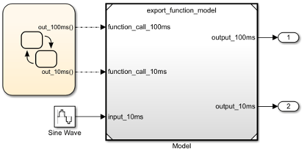
Add a Model block to a new Simulink model. In the Model name box, enter the name of an export-function model. For example, use the export-function model created in Create Export-Function Model.
Add and connect Outport blocks to the output_100ms and output_10ms ports for saving simulation data.
Add a Sine Wave block to provide data input. Set Amplitude to
2and Sample time to0.01. Connect the block to the input_10ms input port on the Model block.
Create Periodic Scheduler Using Stateflow Chart
Create a Stateflow chart. This step requires a Stateflow license.
On the Modeling tab and from the Design section, select Model Explorer
 . In the Model
Hierarchy pane, select
. In the Model
Hierarchy pane, select Chart.Add function-call events with output ports to the chart. From the menu, select Add > Event. In the Name box, enter
out_100ms. From the Scope list, selectOutput to Simulink. Repeat this step to create a function-call event and output port forout_10ms.
Open the chart by double-clicking the block. Add a State block and a Default transition arrow.
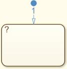
Rename the state to
function_call_scheduler.Add periodic function-calls every 10 and 100 milliseconds. In the state block, enter these commands.
on every(10, tick):send(out_10ms);
on every(100, tick):send(out_100ms);
The keyword
tickis an implicit event that counts the number of simulation steps whilesendis an explicit event that outputs a function-call event to the output ports.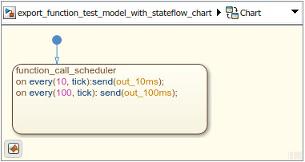
Create Test Model (Harness) for Simulation
Use a Simulink test model only for simulation. After simulation testing, generate code from the export-function model. Then, integrate exported function code with an externally coded scheduler.
Add a Stateflow chart to your test model.
Connect the Stateflow chart outputs to Model block inputs.
Scheduling Restrictions for Referenced Export-Function Models
If a test model references an export-function model, there are some restrictions to ensure consistency with simulation results.
For the test model:
Function-calls to the input ports on the Model block must follow the execution order of the root-level function-call Inport blocks in the referenced export-function model.
If the test model calls the referenced model functions out of order at any time step, the software displays an error. For information on sorted execution order, see Control and Display Execution Order. To disable this restriction, clear the configuration parameter Enable strict scheduling checks for referenced models.
For the export-function model:
The sample times for the root-level function-call Inport blocks must be set to inherited (
-1) or match the sample time of the function-calls from the Stateflow chart that drives them.
Prepare Export-Function Model for Simulation
Before you test the export-function model, configure model settings and specify signals to log.
On the Modeling tab, click Model Settings
 .
.On the Model Referencing pane, clear the configuration parameter Enable strict scheduling check for referenced models.
Verify the settings for these configuration parameters on the Solver pane:
Type is set to
Fixed-step.Solver is set to
discrete (no continuous states).Fixed-step size (fundamental sample time) is set to
auto.
Set up logging for signals. Right-click a signal you want to log, and then click the Log Signals button
 . In this example, the export-function model output signals are logged because they connect to Outport blocks.
Note
When using export-function models in top-model simulations, do not change the enable/disable status of the model during simulation. Enable it at the start of simulation and use function-calls to call it
Test Export-Function Model Using Stateflow Chart
To test and observe the export-function model behavior before generating code, simulate the completed test model.
Optionally, open and simulate the completed test model named ex_export_function_test_model_with_stateflow_chart.
To view the simulation results, open the Simulation Data Inspector. On the Simulation tab, click Data Inspector.

After you test your model, you can generate code for the functions. See Generate Code for Export-Function Model.