Trajectory Follower with RoadRunner Scenario and Simulink 3D Animation
R2026bThis example shows how to co-simulate a Simulink® trajectory follower with a RoadRunner Scenario and visualize the scenario in the 3D environment using Simulink® 3D Animation™.
Introduction
RoadRunner Scenario is an interactive editor that allows you to design scenarios for simulating and testing automated driving systems. You can place vehicles, define their paths and speeds, and then co-simulate the scenario with Simulink.
When you use a RoadRunner scenario as the scene source for the 3D simulation environment, all the actors defined in the RoadRunner scenario are automatically available in the 3D environment. You do not need to manually recreate RoadRunner actors using separate Simulation 3D actor blocks. You can mount a Simulation 3D Camera block directly to a RoadRunner actor to capture image, depth, and semantic segmentation data during co-simulation.
This example extends the Trajectory Follower with RoadRunner Scenario (Automated Driving Toolbox) example by adding a 3D Simulation subsystem to the Simulink model. The trajectory follower controls the ego vehicle. The 3D Simulation subsystem renders the scenario in the 3D environment and captures camera outputs. The 3D Simulation subsystem provides visualization and synthetic sensor outputs only and does not control the ego vehicle.
To use the 3D Simulation subsystem, configure the RoadRunner actor behavior to point to a Simulink model. The Simulation 3D blocks run as part of the Simulink behavior model during RoadRunner co-simulation.
In this example, you:
Set up the environment — Start RoadRunner and copy the required files.
Open the RoadRunner scenario — Open a multi-lane highway scenario.
Explore the Simulink model — Review the trajectory follower model and the
3D Simulationsubsystem.Configure the 3D simulation — Set the scenario in the Simulation 3D Scene Configuration block.
Co-simulate the scenario — Run the co-simulation and inspect camera outputs.
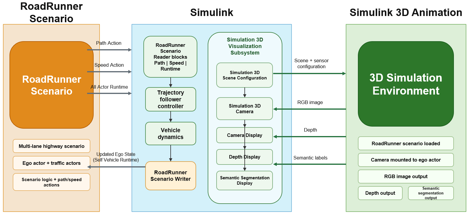
The diagram shows an overview of the information exchanged among RoadRunner Scenario, Simulink, and Simulink 3D Animation.
clear
clc
close all
Set Up Environment
Start the RoadRunner application interactively by using the roadrunnerSetup (Automated Driving Toolbox) function. When the function opens a dialog box, specify the RoadRunner Project Folder and RoadRunner Installation Folder locations.
rrApp = roadrunnerSetup;
This example uses two supporting files:
scenario_TF_MultiLaneHighway.rrscenario— RoadRunner scenario file containing a multi-lane highway scene with an ego vehicle and traffic actors.TrajectoryFollowerSim3D.rrbehavior.rrmeta— Behavior file that associates the Simulink trajectory follower model (TrajectoryFollowerWithRRScenarioSim3D.slx) with the ego vehicle in RoadRunner Scenario.
Copy these files to the RoadRunner project so that the scenario and behavior are available when the simulation runs.
scenarioFile = "scenario_TF_MultiLaneHighway.rrscenario";
behaviorFile = "TrajectoryFollowerSim3D.rrbehavior.rrmeta";

scenarioFolder = fullfile(rrApp.status.Project.Filename,"Scenarios");
behaviorFolder = fullfile(rrApp.status.Project.Filename,"Assets","Behaviors");

copyfile(scenarioFile,scenarioFolder,"f");
copyfile(behaviorFile,behaviorFolder,"f");
Open RoadRunner Scenario
Open the RoadRunner scenario. This scenario defines a multi-lane highway with an ego vehicle that follows a specified path and traffic actors that interact with the ego vehicle.
openScenario(rrApp,scenarioFile);
Connect to the RoadRunner Scenario server for co-simulation by using the createSimulation (Automated Driving Toolbox) function. Use the returned ScenarioSimulation (Automated Driving Toolbox) object to configure simulation parameters and start the co-simulation.
rrSim = rrApp.createSimulation;
Connection status: 1
Connected to RoadRunner Scenario server on localhost:54322, with client id {9d2807b5-b2c0-4509-983e-5594532f5273}
Explore Trajectory Follower Model
Open the Simulink model that implements the trajectory follower behavior and contains the 3D Simulation subsystem.
modelName = "TrajectoryFollowerWithRRScenarioSim3D";
open_system(modelName);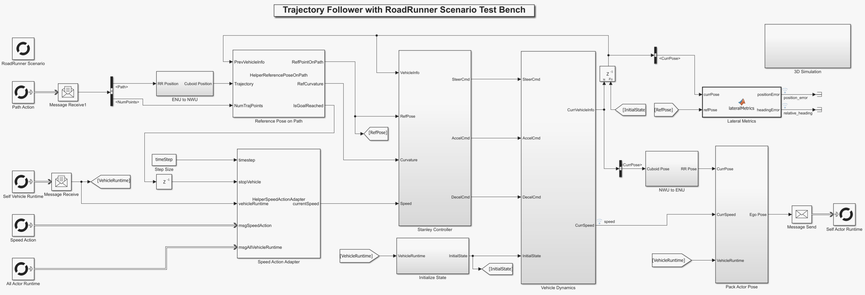
The model has two parallel paths:
Trajectory follower path — Reads path, speed, and actor run-time data from RoadRunner Scenario, computes the ego vehicle pose using a Stanley controller and 3DOF vehicle dynamics, and writes the updated pose back to RoadRunner Scenario.
3D Simulation path — Renders the RoadRunner scenario in the 3D simulation environment and captures camera sensor data from the ego vehicle. This path is for visualization only and does not affect ego vehicle control.
For more details on the trajectory following approach, see Trajectory Follower with RoadRunner Scenario (Automated Driving Toolbox).
Configure 3D Simulation
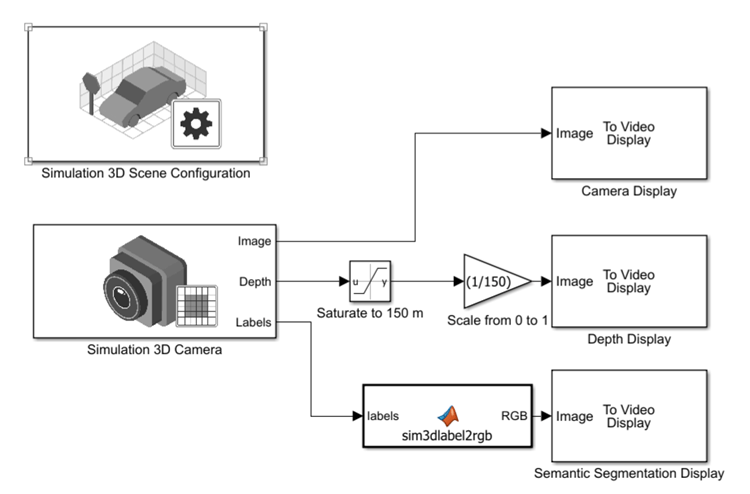
The 3D Simulation subsystem contains these blocks:
Simulation 3D Scene Configuration — Loads the RoadRunner scenario into the 3D simulation environment. Because the RoadRunner scenario is used as the scene source, all scenario actors are automatically created in the 3D world.
Simulation 3D Camera — Captures image, depth, and semantic segmentation data from the ego vehicle perspective.
To Video Display blocks named
Camera Display,Depth Display, andSemantic Segmentation Display— Show the camera output signals during simulation.
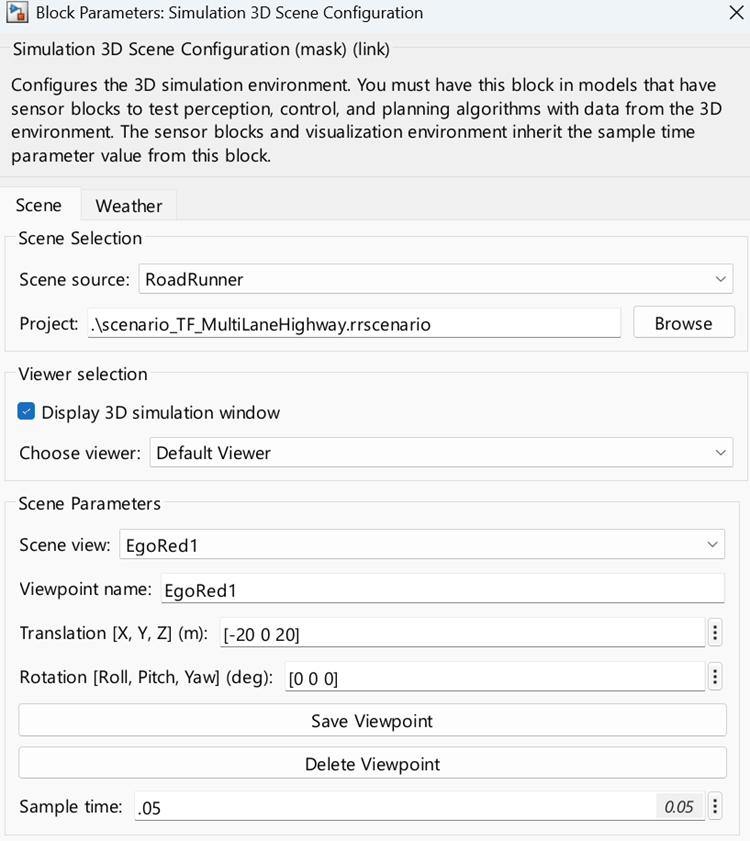
To import the RoadRunner scenario into the 3D environment, set these parameters of the Simulation 3D Scene Configuration block:
Scene source: Set to
RoadRunnerto load all scenario actors automatically into the 3D world.Project: Specify the RoadRunner scenario (
.rrscenario) file.Scene view: Set to
EgoRed1, which is the name of the ego actor in the RoadRunner scenario.Translation [X, Y, Z] (m): Set to
[-20 0 20]to position the viewpoint behind and above the ego vehicle.Sample time: Set to
0.05to match the Simulink model and RoadRunner simulation step size.
To mount the camera on the ego actor, set these parameters of the Simulation 3D Camera block:
Parent name: Set to
Custom.Custom parent name: Set to
EgoRed1. This value must match the RoadRunner actor name to attach the camera correctly.Coordinate system: Set to
ISO8855.Relative translation [X, Y, Z]: Set to
[0.95, 0, 1.15]to place the camera at the front windshield of the vehicle.Relative rotation [Roll, Pitch, Yaw]: Set to
[0, 0, 0]to point the camera forward along the vehicle.
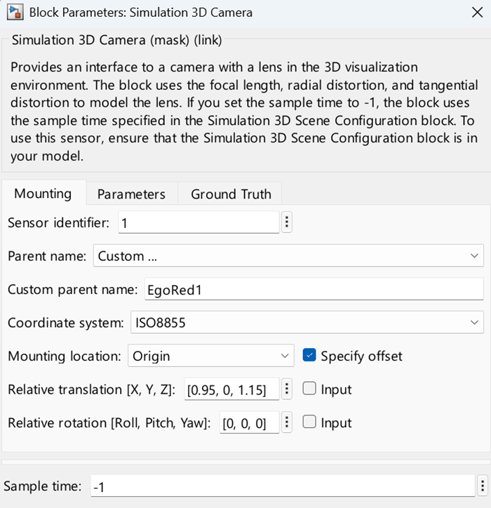
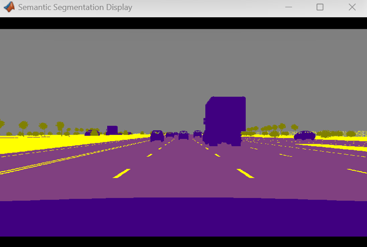
The camera outputs three signals. The model displays the RGB image directly. For the depth output, the model scales the values for better visualization contrast. For the semantic segmentation output, the model converts numeric labels to an RGB colormap using the sim3dColormap helper function.
If you use a different RoadRunner scenario or rename the ego actor, update the Scene view parameter in the Simulation 3D Scene Configuration block and the Custom parent name parameter in the Simulation 3D Camera block.
Co-Simulate Scenario with Trajectory Follower Behavior
Assign the Simulink trajectory follower behavior to the ego vehicle by setting the egoBehavior scenario variable to the behavior asset path.
rrApp.setScenarioVariable("egoBehavior", ...
    "<PROJECT>/Assets/Behaviors/TrajectoryFollowerSim3D.rrbehavior");
Initialize the trajectory follower model parameters using the helperSLTrajectoryFollowerWithRRScenarioSetup function. Set MaxPathPoints to 5000 to accommodate the longer multi-lane highway path.
helperSLTrajectoryFollowerWithRRScenarioSetup(MaxPathPoints=5000);
Set the RoadRunner Scenario simulation step size to match the Simulink model step size of 0.05 seconds. The Simulation 3D Scene Configuration block also uses this value to synchronize the 3D rendering.
rrSim.set("StepSize",timeStep);Run the co-simulation and wait for it to complete.
rrSim.set("SimulationCommand","Start");
while strcmp(rrSim.get("SimulationStatus"),"Running")
    pause(1);
end
Expected Results
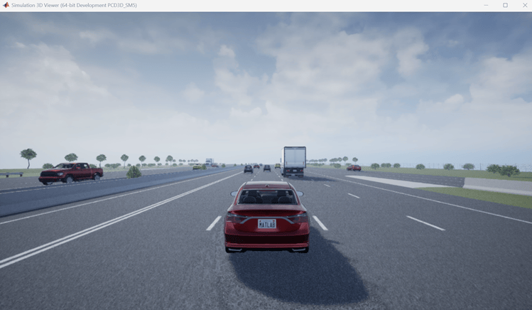
When the simulation starts, RoadRunner runs the scenario with the Simulink trajectory follower behavior assigned to the ego vehicle. The 3D simulation environment opens and renders the same RoadRunner scenario.
The displays in the 3D Simulation subsystem show:
RGB camera output
Depth output
Semantic segmentation output from the ego-mounted camera
Inspect Simulation Results
During the co-simulation, the trajectory follower and the 3D Simulation subsystem operate in parallel. The scenario is rendered in the 3D environment along with the camera outputs.
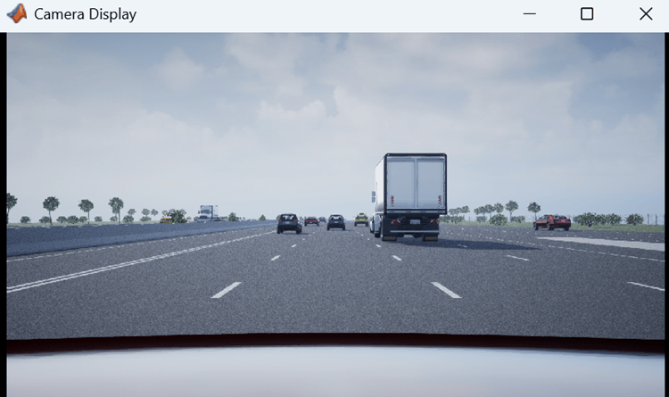
Camera Display — Front-facing camera view of the ego vehicle.
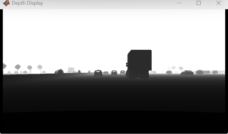
Depth Display — Pixel-level distance of objects from the camera. This view is useful for depth estimation.
Semantic Segmentation Display — Pixel-level classification of scene elements such as road, vehicle, vegetation, and sky. This view is useful for perception algorithm development.
You can use these synthetic sensor outputs to develop and test perception algorithms or to visually validate the trajectory follower behavior in a photorealistic 3D scene. Because the RoadRunner scenario is the scene source, all traffic actors from the scenario appear in the 3D environment without requiring additional Simulation 3D actor blocks.
See Also
Blocks
- Simulation 3D Scene Configuration | Simulation 3D Camera | RoadRunner Scenario (Automated Driving Toolbox) | RoadRunner Scenario Writer (Automated Driving Toolbox) | RoadRunner Scenario Reader (Automated Driving Toolbox)
Objects
ScenarioSimulation(Automated Driving Toolbox)
Topics
- Create 3D Simulations in Unreal Engine Environment
- Unreal Engine Simulation Environment Requirements and Limitations
- Trajectory Follower with RoadRunner Scenario (Automated Driving Toolbox)
- Autonomous Emergency Braking with High-Fidelity Vehicle Dynamics (Automated Driving Toolbox)

