Three-Phase Transformer Inductance Matrix Type (Two Windings)
(To be removed) Implement three-phase two-winding transformer with configurable winding connections and core geometry
The Specialized Power Systems library will be removed in R2026a. Use the Simscape™ Electrical™ blocks and functions instead. For more information on updating your models, see Upgrade Specialized Power Systems Models to use Simscape Electrical Blocks.
Library
Simscape / Electrical / Specialized Power Systems / Power Grid Elements
Description
The Three-Phase Transformer Inductance Matrix Type (Two Windings) block is a three-phase transformer with a three-limb core and two windings per phase. Unlike the Three-Phase Transformer (Two Windings) block, which is modeled by three separate single-phase transformers, this block takes into account the couplings between windings of different phases. The transformer core and windings are shown in the following illustration.
![]()
The phase windings of the transformer are numbered as follows:
1 and 4 on phase A
2 and 5 on phase B
3 and 6 on phase C
This core geometry implies that phase winding 1 is coupled to all other phase windings (2 to 6), whereas in Three-Phase Transformer (Two Windings) block (a three-phase transformer using three independent cores) winding 1 is coupled only with winding 4.
Note
The phase winding numbers 1 and 2 should not be confused with the numbers used to identify the three-phase windings of the transformer. Three-phase winding 1 consists of phase windings 1,2,3, and three-phase winding 2 consists of phase windings 4,5,6.
Transformer Model
The Three-Phase Transformer Inductance Matrix Type (Two Windings) block implements the following matrix relationship:
R1 to R6 represent the winding resistances. The self-inductance terms Lii and the mutual inductance terms Lij are computed from the voltage ratios, the inductive component of the no load excitation currents and the short-circuit reactances at nominal frequency. Two sets of values in positive-sequence and in zero-sequence allow calculation of the 6 diagonal terms and 15 off-diagonal terms of the symmetrical inductance matrix.
When the parameter Core type is set to Three
single-phase cores, the model uses two independent circuits with (3x3) R and L
matrices. In this condition, the positive-sequence and zero-sequence parameters are identical
and you only specify positive-sequence values.
The self and mutual terms of the (6x6) L matrix are obtained from excitation currents (one three-phase winding is excited and the other three-phase winding is left open) and from positive- and zero-sequence short-circuit reactances X112 and X012 measured with three-phase winding 1 excited and three-phase winding 2 short-circuited.
Assuming the following positive-sequence parameters:
Q11= Three-phase reactive power absorbed by winding 1 at no load when winding 1 is excited by a positive-sequence voltage Vnom1 with winding 2 open
Q12= Three-phase reactive power absorbed by winding 2 at no load when winding 2 is excited by a positive-sequence voltage Vnom2 with winding 1 open
X112= Positive-sequence
short-circuit reactance seen from winding 1
when winding 2 is
short-circuited
Vnom1, Vnom2= Nominal line-line voltages of windings 1 and 2
The positive-sequence self and mutual reactances are given by:
The zero-sequence self-reactances X0(1,1), X0(2,2), and mutual reactance X0(1,2) = X0(2,1) are also computed using similar equations.
Extension from the following two (2x2) reactance matrices in positive-sequence and in zero-sequence
to a (6x6) matrix, is performed by replacing each of the four [X1 X0] pairs by a (3x3) submatrix of the form:
where the self and mutual terms are given by:
Xs =
(X0 +
2X1)/3
Xm
= (X0 –
X1)/3
In order to model the core losses (active power P1 and P0 in positive- and zero-sequences), additional shunt resistances are also connected to terminals of one of the three-phase windings. If winding 1 is selected, the resistances are computed as:
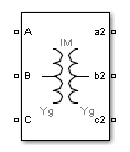
The block takes into account the connection type you select, and the icon of the block is
automatically updated. An input port labeled N is added to the block if you
select the Y connection with accessible neutral for winding 1. If you ask for an accessible
neutral on winding 2, an extra outport port labeled n2 is generated.
Often, the zero-sequence excitation current of a transformer with a 3-limb core is not provided by the manufacturer. In such a case, a reasonable value can be guessed as explained below.
The following figure shows a three-limb core with a single three-phase winding. Only phase B is excited and voltage is measured on phase A and phase C. The flux Φ produced by phase B shares equally between phase A and phase C so that Φ/2 is flowing in limb A and in limb C. Therefore, in this particular case, if leakage inductance of winding B would be zero, voltage induced on phases A an C would be -k.VB=-VB/2. In fact, because of the leakage inductance of the three windings, the average value of induced voltage ratio k when windings A, B, and C are successively excited must be slightly lower than 0.5.
Assume:
Zs = average value of the three
self-impedances
Zm =average
value of mutual impedance between phases
Z1 = positive-sequence
impedance of three-phase winding
Z0 = zero-sequence impedance of
three-phase winding
I1 =
positive-sequence excitation current
I0 = zero-sequence excitation
current
where k= ratio of induced voltage (with k slightly lower than 0.5)
Therefore, the I0/I1 ratio can be deduced from k:
Obviously k cannot be exactly 0.5 because this would lead to an infinite zero-sequence current. Also, when the three windings are excited with a zero-sequence voltage, the flux path should return through the air and tank surrounding the iron core. The high reluctance of the zero-sequence flux path results in a high zero-sequence current.
Let us assume I1= 0.5%. A reasonable value for I0 could be 100%. Therefore I0/I1=200. According to the equation for I0/I1 given above, one can deduce the value of k. k=(200-1)/(2*200+1)= 199/401= 0.496.
Zero-sequence losses should be also higher than the positive-sequence losses because of the additional eddy current losses in the tank.
Finally, the value of the zero-sequence excitation current and the value of the zero-sequence losses are not critical if the transformer has a winding connected in Delta because this winding acts as a short circuit for zero-sequence.
The three-phase windings of the transformer can be connected in the following manner:
Y
Y with accessible neutral
Grounded Y
Delta (D1), delta lagging Y by 30 degrees
Delta (D11), delta leading Y by 30 degrees
Note
The D1 and D11 notations refer to the following clock convention. It assumes that the reference Y voltage phasor is at noon (12) on a clock display. D1 and D11 refer respectively to 1 PM (delta voltages lagging Y voltages by 30 degrees) and 11 AM (delta voltages leading Y voltages by 30 degrees).
Parameters
Configuration Tab
- Core type
Select the core geometry:
Three single-phase coresorThree-limb or five-limb core(default). If you select the first option, only the positive-sequence parameters are used to compute the inductance matrix. If you select the second option, both the positive- and zero-sequence parameters are used.- Winding 1 connection
The winding connection for three-phase winding 1. Choices are
Y,Yn,Yg(default),Delta (D1), andDelta (D11).- Winding 2 connection
The winding connection for three-phase winding 2. Choices are
Y,Yn,Yg(default),Delta (D1), andDelta (D11).- Connect windings 1 and 2 in autotransformer
Select to connect the three-phase windings 1 and 2 in autotransformer (three-phase windings 1 and 2 in series with additive voltage). Default is cleared.
If the first voltage specified in the Nominal line-line voltages parameter is higher than the second voltage, the low voltage tap is connected on the right side (a2,b2,c2 terminals). Otherwise, the low voltage tap is connected on the left side (A,B,C terminals).
In autotransformer mode you must specify the same winding connections for the three-phase windings 1 and 2. If you select
Ynconnection for both winding 1 and winding 2, the common neutral N connector is displayed on the left side.The following figure illustrates winding connections for one phase of an autotransformer when the three-phase windings are both connected in Yg.
If V1 > V2:
If V2 > V1:
Windings W1,W2,W3 correspond to the following phase winding numbers:
Phase A: W1=1, W2=4
Phase B: W1=2, W2=5
Phase C: W1=3, W2=6
- Measurements
Select
Winding voltagesto measure the voltage across the winding terminals of the Three-Phase Transformer block.Select
Winding currentsto measure the current flowing through the windings of the Three-Phase Transformer block.Select
All measurementsto measure the winding voltages and currents.Default is
None.Place a Multimeter block in your model to display the selected measurements during the simulation. In the Available Measurements list box of the Multimeter block, the measurements are identified by a label followed by the block name.
If the Winding 1 connection parameter is set to
Y,Yn, orYg, the labels are as follows.Measurement
Label
Winding 1 voltages
Uan_w1:or
Uag_w1:Winding 1 currents
Ian_w1:or
Iag_w1:If the Winding 1 connection parameter is set to
Delta (D11)orDelta (D1), the labels are as follows.Measurement
Label
Winding 1 voltages
Uab_w1:Winding 1 currents
Iab_w1:The same labels apply for three-phase winding 2, except that
1is replaced by2in the labels.
Parameters Tab
- Nominal power and frequency
The nominal power rating, in volt-amperes (VA), and nominal frequency, in hertz (Hz), of the transformer. Default is
[100e3, 60].- Nominal line-line voltages [V1 V2]
The phase-to-phase nominal voltages of windings 1 and 2 in volts RMS. Default is
[2400, 600].- Winding resistances [R1 R2]
The resistances in pu for windings 1 and 2. Default is
[0.01, 0.01].- Positive-sequence no-load excitation current
The no-load excitation current in percent of the nominal current when positive-sequence nominal voltage is applied at any three-phase winding terminals (ABC or abc2). Default is
2.- Positive-sequence no-load losses
The core losses plus winding losses at no-load, in watts (W), when positive-sequence nominal voltage is applied at any three-phase winding terminals (ABC or abc2). Default is
1000.- Positive-sequence short-circuit reactance
The positive-sequence short-circuit reactances X12 in pu. X12 is the reactance measured from winding 1 when winding 2 is short-circuited. Default is
0.06.When the Connect windings 1 and 2 in autotransformer parameter is selected, the short-circuit reactances is labeled XHL. H and L indicate respectively the high voltage winding (either winding 1 or winding 2) and the low voltage winding (either winding 1 or winding 2).
- Zero-sequence no-load excitation current with Delta windings opened
The no-load excitation current in percent of the nominal current when zero-sequence nominal voltage is applied at any three-phase winding terminals (ABC or abc2) connected in Yg or Yn. Default is
100.Note
If your transformer contains delta-connected windings (D1 or D11), the zero-sequence current flowing into the Yg or Yn winding connected to the zero-sequence voltage source does not represent the net excitation current because zero-sequence currents are also flowing in the delta winding. Therefore, you must specify the no-load zero-sequence circulation current obtained with the delta windings open.
If you want to measure this excitation current, you must temporarily change the delta windings connections from D1 or D11 to Y, Yg, or Yn, and connect the excited winding in Yg or Yn to provide a return path for the source zero-sequence currents.
- Zero-sequence no-load losses with Delta windings opened
The core losses plus winding losses at no-load, in watts (W), when zero-sequence nominal voltage is applied at any group of winding terminals (ABC or abc2) connected in Yg or Yn. The Delta winding must be temporarily open to measure these losses. Default is
1500.Note
If your transformer contains delta-connected windings (D1 or D11), the zero-sequence current flowing into the Yg or Yn winding connected to the zero-sequence voltage source does not represent the net excitation current because zero-sequence currents are also flowing in the delta winding. Therefore, you must specify the no-load zero-sequence circulation current obtained with the delta windings open.
- Zero-sequence short-circuit reactance
The zero-sequence short-circuit reactance X12 in pu. X12 is the reactance measured from winding 1 when winding 2 is short-circuited. Default is
0.03.When the Connect windings 1 and 2 in autotransformer parameter is selected, the short-circuit reactances is labeled XHL. H and L indicate respectively the high voltage winding (either winding 1 or winding 2) and the low voltage winding (either winding 1 or winding 2).
Limitations
This transformer model does not include saturation. If you need modeling saturation, connect the primary winding of a saturable Three-Phase Transformer (Two Windings) in parallel with the primary winding of your model. Use the same connection (Yg, D1 or D11) and same winding resistance for the two windings connected in parallel. Specify the Y or Yg connection for the secondary winding and leave it open. Specify appropriate voltage, power ratings, and saturation characteristics that you want. The saturation characteristic is obtained when the transformer is excited by a positive-sequence voltage.
If you are modeling a transformer with three single-phase cores or a five-limb core, this model produces acceptable saturation currents because flux stays trapped inside the iron core.
For a three-limb core, this saturation model still produces acceptable results, even if zero-sequence flux circulates outside of the core and returns through the air and the transformer tank surrounding the iron core. As the zero-sequence flux circulates in the air, the magnetic circuit is mainly linear and its reluctance is high (high magnetizing currents). These high zero-sequence currents (100% and more of nominal current) required to magnetize the air path are already taken into account in the linear model. Connecting a saturable transformer outside the three-limb linear model with a flux-current characteristic obtained in positive sequence produces currents required for magnetization of the iron core. This model gives acceptable results whether the three-limb transformer has a delta or not.
See Also
Linear Transformer, Multimeter, Three-Phase Transformer (Two Windings), Three-Phase Transformer (Three Windings), Three-Phase Transformer Inductance Matrix Type (Three Windings)
Version History
Introduced in R2008a