Main Content

generateSemiconductorSwitchROM

Generate reduced-order model of semiconductor switch

Since R2024b

Description

The generateSemiconductorSwitchROM function converts a high-fidelity semiconductor switch subsystem into a MOSFET (Ideal, Switching) or IGBT (Ideal, Switching) block, which represent a reduced-order model (ROM). The function parameterizes the ROM with the on-state tabulated I-V curve and tabulated switching losses for the transistor, and the on-state tabulated I-V curve and tabulated reverse recovery loss for the associated body or external diode.

The semiconductor switch in the high-fidelity subsystem can be an N-Channel MOSFET block, an N-Channel IGBT block, a SPICE-Imported MOSFET block, or a black-box semiconductor model. The subsystem must include a body diode or an external diode associated with the semiconductor switch. The generateSemicondutorSwitchROM function uses a double-pulse test circuit to extract the switching losses. The test harness is a single-quadrant chopper that supplies an inductive load. The function requires a diode for the IGBT or MOSFET devices as a free-wheeling diode because, in many applications such as three-phase AC motor drives, bi-directional DC motor drives, and full-bridge DC-DC converters, the power electronics converter comprises one or more IGBT-based half-bridges.

ROMs are easier to interpret and run faster than high-fidelity semiconductor switch subsystems. You can run faster simulations by replacing the original semiconductor switch subsystem with the generated ROM subsystem. Use ROMs to quickly test and analyze system-level scenarios where the semiconductor switch interacts with other systems.

generateSemiconductorSwitchROM(sys) generates a reduced-order model from the high-fidelity semiconductor switch subsystem sys.

example

generateSemiconductorSwitchROM(sys,Name=Value) specifies options using one or more name-value arguments in addition to the input argument in previous syntaxes. For example, generateSemiconductorSwitchROM(sys,OnStateGateSourceVoltage=20) generates a ROM with an on-state gate-source voltage equal to 20 V.

ROMParameters = generateSemiconductorSwitchROM(sys,Name=Value) returns a structure that contains the lookup table data for the I-V curve and loss of the semiconductor switch and the diode.

Examples

collapse all

This example shows how to generate the reduced order model (ROM) of an N-Channel MOSFET subsystem.

Open Model

Open the GenerateROMOfThresholdBasedMOSFETModel.slx model.

open_system("GenerateROMOfThresholdBasedMOSFET");

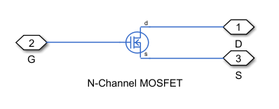
The Gate Driver block that drives the MOSFET device has an on-state gate-source voltage of 10 V, an on-state gate drive resistance of 2 Ohm, and an off-state gate drive resistance of 2 Ohm. The ThresholdBasedMOSFET subsystem contains an N-Channel MOSFET block.

The subsystem must have the correct port names and port types. The ports of the subsystem must match the ports of the N-Channel MOSFET block: G, D, and S.

To include the temperature dependence in your ROM model, specify the device simulation temperature by using the Tdevice workspace variable. The generateSemiconductorSwitchROM function sets the Device simulation temperature parameter of the generated ROM to the values you specify in the Temperatures name-value argument.

Generate ROM

Run the generateSemiconductorSwitchROM function to generate the ROM of the ThresholdBasedMOSFET subsystem and set these options:

  • Based on the gate driver specifications, set the on-state gate-source voltage to 10 V, the on-state gate drive resistance to 2 Ohm, and the off-state gate drive resistance to 2 Ohm.

  • Calculate the I-V curves and the losses at two different temperatures, 25°C and 75°C.

  • Specify the lookup table breakpoints for the I-V characteristics and losses.

ROMParameters = generateSemiconductorSwitchROM("GenerateROMOfThresholdBasedMOSFET/ThresholdBasedMOSFET", ...
                    DeviceType="MOSFET", ...
                    OnStateGateSourceVoltage=10, ...
                    OnStateGateResistance=2, ...
                    OffStateGateResistance=2, ...
                    Temperatures=[25, 75], ...
                    OnStateCurrentsForIV= 0:1:70, ...
                    OnStateCurrentsForLoss=[10, 30, 50, 70], ...
                    OffStateVoltagesForLoss=[80,100]);
Using:
  DeviceType = MOSFET
  OnStateGateSourceVoltage = 10
  ConstantCurrentForThresholdVoltage = 0.1
  OnStateGateResistance = 2
  OffStateGateResistance = 2
  Temperatures = [25;75]
  OnStateCurrentsForIV = [0;1;2;3;4;5;6;7;8;9;10;11;12;13;14;15;16;17;18;19;20;21;22;23;24;25;26;27;28;29;30;31;32;33;34;35;36;37;38;39;40;41;42;43;44;45;46;47;48;49;50;51;52;53;54;55;56;57;58;59;60;61;62;63;64;65;66;67;68;69;70]
  OnStateCurrentsForLoss = [0;10;30;50;70]
  OffStateVoltagesForLoss = [0;80;100]
  MaximumSwitchingFrequency = 100000
  TestCircuitLeakageInductance = 0
  TestCircuitStrayCapacitance = 0
Writing test harness models in the folder '/tmp/Bdoc24b_2725827_2713767/'
Extracting switch IV curve ...
Running simulation to extract the threshold voltage ...
Threshold voltage extracted = 1.8569
Running simulation to estimate voltage for current = 70 [A] and temperature = 25 [degC] ...
Estimated voltage = 1.8199 [V].
Running voltage sweep simulation between 0 and 2.3658 [V] at constant temperature = 25 [degC] ...
Running voltage sweep simulation between 0 and 2.3658 [V] at constant temperature = 75 [degC] ...
Running voltage sweep simulation between 0 and 2.2752 [V] at constant temperature = 25 [degC] ...

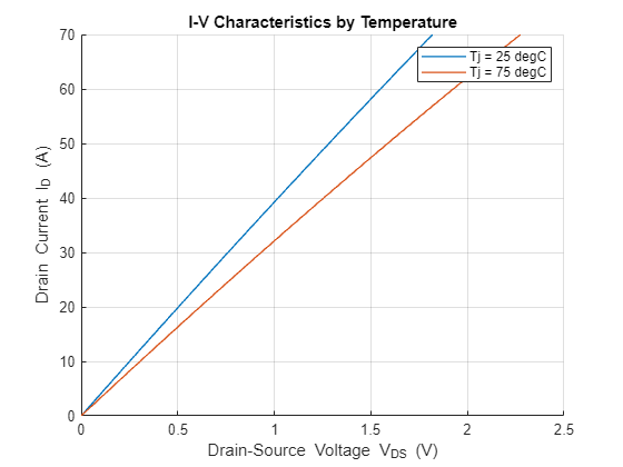
Figure contains an axes object. The axes object with title I-V Characteristics by Temperature, xlabel Drain-Source blank Voltage blank V indexOf DS baseline blank (V), ylabel Drain Current I indexOf D baseline blank (A) contains 2 objects of type line. These objects represent Tj = 25 degC, Tj = 75 degC.

Extracting diode IV curve ...
Running simulation to estimate voltage for current = -70 [A] and temperature = 25 [degC] ...
Estimated voltage = -9.2618 [V].
Running voltage sweep simulation between 0 and -12.0404 [V] at constant temperature = 25 [degC] ...
Running voltage sweep simulation between 0 and -12.0404 [V] at constant temperature = 75 [degC] ...

Figure contains an axes object. The axes object with title Diode I-V Characteristics by Temperature, xlabel Diode forward voltage V indexOf f baseline [V], ylabel Diode forward current I indexOf f baseline [A] contains 2 objects of type line. These objects represent Tj = 25 degC, Tj = 75 degC.

Extracting switching loss lookup tables ...
Running simulation to extract switching losses at T = 25 [degC], Iload = 10 [A], and Vcc = 80 [V] ...
Estimated Eon = 1.1497e-06 [J] and Eoff = 7.4105e-07 [J].
Estimated Erec = 2.3128e-07 [J].
Running simulation to extract switching losses at T = 25 [degC], Iload = 10 [A], and Vcc = 100 [V] ...
Estimated Eon = 1.7767e-06 [J] and Eoff = 1.2985e-06 [J].
Estimated Erec = 3.9158e-07 [J].
Running simulation to extract switching losses at T = 25 [degC], Iload = 30 [A], and Vcc = 80 [V] ...
Estimated Eon = 3.5982e-06 [J] and Eoff = 2.3259e-06 [J].
Estimated Erec = 2.849e-07 [J].
Running simulation to extract switching losses at T = 25 [degC], Iload = 30 [A], and Vcc = 100 [V] ...
Estimated Eon = 5.4575e-06 [J] and Eoff = 3.3081e-06 [J].
Estimated Erec = 3.9772e-07 [J].
Running simulation to extract switching losses at T = 25 [degC], Iload = 50 [A], and Vcc = 80 [V] ...
Estimated Eon = 6.8303e-06 [J] and Eoff = 3.3279e-06 [J].
Estimated Erec = 3.4697e-07 [J].
Running simulation to extract switching losses at T = 25 [degC], Iload = 50 [A], and Vcc = 100 [V] ...
Estimated Eon = 1.0312e-05 [J] and Eoff = 5.1715e-06 [J].
Estimated Erec = 4.8426e-07 [J].
Running simulation to extract switching losses at T = 25 [degC], Iload = 70 [A], and Vcc = 80 [V] ...
Estimated Eon = 1.1033e-05 [J] and Eoff = 4.4236e-06 [J].
Estimated Erec = 4.3884e-07 [J].
Running simulation to extract switching losses at T = 25 [degC], Iload = 70 [A], and Vcc = 100 [V] ...
Estimated Eon = 1.6746e-05 [J] and Eoff = 6.4921e-06 [J].
Estimated Erec = 5.5979e-07 [J].
Running simulation to extract switching losses at T = 75 [degC], Iload = 10 [A], and Vcc = 80 [V] ...
Estimated Eon = 1.2777e-06 [J] and Eoff = 6.4168e-07 [J].
Estimated Erec = 2.343e-07 [J].
Running simulation to extract switching losses at T = 75 [degC], Iload = 10 [A], and Vcc = 100 [V] ...
Estimated Eon = 1.9585e-06 [J] and Eoff = 9.9713e-07 [J].
Estimated Erec = 3.4313e-07 [J].
Running simulation to extract switching losses at T = 75 [degC], Iload = 30 [A], and Vcc = 80 [V] ...
Estimated Eon = 4.3152e-06 [J] and Eoff = 1.9423e-06 [J].
Estimated Erec = 3.0316e-07 [J].
Running simulation to extract switching losses at T = 75 [degC], Iload = 30 [A], and Vcc = 100 [V] ...
Estimated Eon = 6.5522e-06 [J] and Eoff = 3.0452e-06 [J].
Estimated Erec = 4.4141e-07 [J].
Running simulation to extract switching losses at T = 75 [degC], Iload = 50 [A], and Vcc = 80 [V] ...
Estimated Eon = 8.7832e-06 [J] and Eoff = 3.0693e-06 [J].
Estimated Erec = 3.9435e-07 [J].
Running simulation to extract switching losses at T = 75 [degC], Iload = 50 [A], and Vcc = 100 [V] ...
Estimated Eon = 1.313e-05 [J] and Eoff = 4.5401e-06 [J].
Estimated Erec = 5.3099e-07 [J].
Running simulation to extract switching losses at T = 75 [degC], Iload = 70 [A], and Vcc = 80 [V] ...
Estimated Eon = 1.5219e-05 [J] and Eoff = 3.8334e-06 [J].
Estimated Erec = 5.2944e-07 [J].
Running simulation to extract switching losses at T = 75 [degC], Iload = 70 [A], and Vcc = 100 [V] ...
Estimated Eon = 2.2885e-05 [J] and Eoff = 5.7748e-06 [J].
Estimated Erec = 6.6468e-07 [J].

Figure Eon contains 2 axes objects. Axes object 1 with title Turn-On Switching Loss (Eon) at Tj = 25 [degC], xlabel On-state current [A], ylabel Energy loss (Eon) [J] contains 3 objects of type line. These objects represent Off-state voltage = 0 [V], Off-state voltage = 80 [V], Off-state voltage = 100 [V]. Axes object 2 with title Turn-On Switching Loss (Eon) at Tj = 75 [degC], xlabel On-state current [A], ylabel Energy loss (Eon) [J] contains 3 objects of type line. These objects represent Off-state voltage = 0 [V], Off-state voltage = 80 [V], Off-state voltage = 100 [V].

Figure Eoff contains 2 axes objects. Axes object 1 with title Turn-Off Switching Loss (Eoff) at Tj = 25 [degC], xlabel On-state current [A], ylabel Energy loss (Eoff) [J] contains 3 objects of type line. These objects represent Off-state voltage = 0 [V], Off-state voltage = 80 [V], Off-state voltage = 100 [V]. Axes object 2 with title Turn-Off Switching Loss (Eoff) at Tj = 75 [degC], xlabel On-state current [A], ylabel Energy loss (Eoff) [J] contains 3 objects of type line. These objects represent Off-state voltage = 0 [V], Off-state voltage = 80 [V], Off-state voltage = 100 [V].

Figure Erec contains 2 axes objects. Axes object 1 with title Reverse Recovery Loss (Erec) at Tj = 25 [degC], xlabel Complementary switch initial current [A], ylabel Energy loss (Erec) [J] contains 3 objects of type line. These objects represent Off-state voltage = 0 [V], Off-state voltage = 80 [V], Off-state voltage = 100 [V]. Axes object 2 with title Reverse Recovery Loss (Erec) at Tj = 75 [degC], xlabel Complementary switch initial current [A], ylabel Energy loss (Erec) [J] contains 3 objects of type line. These objects represent Off-state voltage = 0 [V], Off-state voltage = 80 [V], Off-state voltage = 100 [V].

ans = 
"untitled/MOSFETROM/MOSFET (Ideal, Switching)"
ROM generation complete.

Input Arguments

collapse all

Block path to the semiconductor switch subsystem from which the function generates the ROM, specified as a character vector or a string.

The semiconductor switch in the high-fidelity subsystem can be an N-Channel MOSFET block, an N-Channel IGBT block, a SPICE-Imported MOSFET block, or a black-box semiconductor model. The subsystem must include a body diode or an external diode associated with the semiconductor switch.

Name-Value Arguments

Specify optional pairs of arguments as Name1=Value1,...,NameN=ValueN, where Name is the argument name and Value is the corresponding value. Name-value arguments must appear after other arguments, but the order of the pairs does not matter.

Example: generateSemiconductorSwitchROM(DeviceType="MOSFET",OnStateGateSourceVoltage=10,OnStateGateResistance=2);

Option to specify the semiconductor device type inside the semiconductor switch subsystem, specified as "MOSFET" or "IGBT".

On-state gate-source voltage, in volts, specified as a positive scalar.

Constant current for the threshold voltage, in amperes, specified as a positive scalar.

On-state gate resistance, in ohms, specified as a positive scalar.

Off-state gate resistance, in ohms, specified as a positive scalar.

Device simulation temperature, in Celsius, specified as a scalar or a vector of breakpoint values for the lookup tables.

On-state current breakpoints, in amperes, for the tabulated I-V curves, specified as a vector of nonnegative scalars.

On-state current breakpoints for switching losses, in amperes, specified as a vector of nonnegative scalars. The switching losses must include the turn-on switching loss, Eon, the turn-off switching loss, Eoff, and the reverse recovery loss, Erec.

Off-state voltage breakpoints for losses, in volts, specified as a vector of nonnegative scalars. The switching losses must include the turn-on switching loss, Eon, the turn-off switching loss, Eoff, and the reverse recovery loss, Erec.

Leakage inductance of the test circuit, in henry, specified as a nonnegative scalar.

Stray capacitance of the test circuit, in farads, specified as a nonnegative scalar.

Option to display the progress of the function and results, specified as true or false. To display the results, you must set CreateModel to true.

Option to create a Simulink model that contains the ROM, specified as true or false.

Folder to read and write the ROM-generation test harness models, specified as a string. If you set the value of this parameter to "", the software writes the models in the temporary folder specified by the tempdir command.

Output Arguments

collapse all

ROM parameters that the function generates from the semiconductor switch subsystem, returned as a structure with these fields.

Lookup table for the I-V curve and loss of the semiconductor switch, returned as a structure.

Lookup table for the I-V curve and loss of the diode, returned as a structure.

Version History

Introduced in R2024b