Hall-Effect Rotary Encoder
Four-element Hall-effect rotary encoder

Libraries:
Simscape /
Electrical /
Sensors & Transducers
Description
The Hall-Effect Rotary Encoder block models a 360° rotary position sensor using four equally spaced Hall elements under a magnetized, rotating magnet. The elements generate four sinusoidal waveforms.
This figure shows a schematic of the encoder. The hall elements, yp, yn, xp, and xn, remain in a fixed position while the north and south poles of the magnet rotate at the angle θ.

Equations
These equations describe the voltages between the elements of the rotary encoder:
where:
vx is the voltage between elements xp and xn;
vy is the voltage between elements yp and yn;
Ax and Ay are the voltage amplitudes for the x and y axes that reflect the sensitivity mismatch;
Vx0 and Vy0 are the voltage offsets for the x and y axes;
β is the quadrature error.
The block uses this equation to decode the angle:
Variables
To set the priority and initial target values for the block variables before simulation, use the Initial Targets section in the block dialog box or Property Inspector. For more information, see Set Priority and Initial Target for Block Variables.
Nominal values provide a way to specify the expected magnitude of a variable in a model. Using system scaling based on nominal values increases the simulation robustness. You can specify nominal values using different sources, including the Nominal Values section in the block dialog box or Property Inspector. For more information, see System Scaling by Nominal Values.
Examples
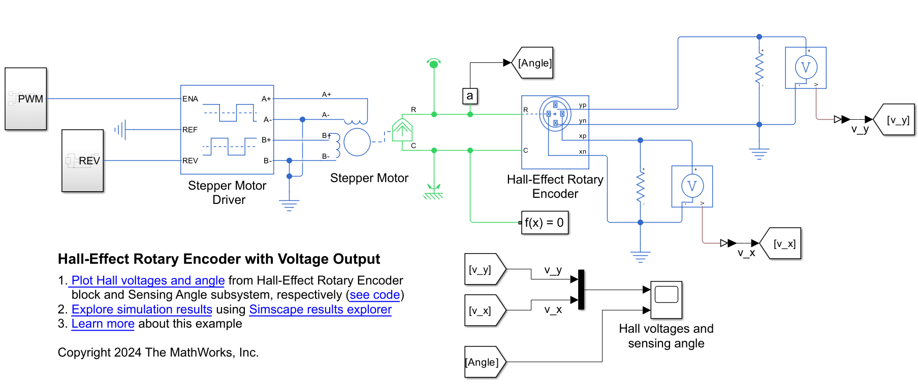
Sense Stepper Motor Angle Using Hall-Effect Encoder
Detect the angle of a stepper motor using a Hall-Effect Rotary Encoder block.
Ports
Output
Conserving
Parameters
Extended Capabilities
Version History
Introduced in R2019b