Stand-Alone Solar PV DC Power System with Battery Backup
This example shows the design of a stand-alone solar photovoltaic (PV) DC power system with battery backup. In this example, you learn how to:
Choose the necessary battery rating based on the connected load profile and available solar power.
Determine how to arrange the panels in terms of the number of series-connected strings and the number of panels per string.
Select a proper PI controller proportional gain,
 , and phase-lead constant,
  .
.
Both solar PV and battery storage support stand-alone loads. The load is connected across the constant DC output. A solar PV system operates in both maximum power point tracking (MPPT) and de-rated voltage control modes. The battery management system (BMS) uses bidirectional DC-DC converters.
A stand-alone PV system requires six normal operating modes based on the solar irradiance, generated solar power, connected load, state of charge of the battery, and maximum battery charging and discharging current limits.
To track the maximum power point (MPP) of solar PV system, you can choose between two MPPT techniques:
Incremental conductance
Perturbation and observation
You can specify the average daily connected load profile, region daily available average solar energy (kWhr), solar PV system operating temperature, day of autonomy, battery recharge time, output DC voltage, and solar panel specification. This example uses solar panel manufacturer data to determine the number of PV panels required to deliver the specified generation capability.
PI controller of the form  controls the solar PV and BMS.
This example uses:
A MATLAB® live script to design the overall standalone PV system.
Simulink® to design/simulate the control logic for the system.
Simscape™ to simulate the power circuit.
Stateflow® to implement the supervisory control logic.
Stand-Alone PV DC Power System Model
To open a script that designs the standalone PV DC power system, at the MATLAB Command Window, enter: edit 'SolarPVDCWithBatteryData'
These are the battery and solar PV plant parameters:
***********************************************************************************************
****          For the Given Stand-Alone PV System, Battery Sizing Parameters           ****
***********************************************************************************************
*** Calculated amphr of the battery  =  542.91 Ahr
*** Battery nominal voltage  =  78 V
*** Battery voltage at 80% discharge  =  70.20 V
*** Number of required battery cell  =  39.00
*** Average discharge current  =  4.28 A
***********************************************************************************************
***********************************************************************************************
****          For the Given Solar Panel, PV Plant Parameters           ****
***********************************************************************************************
*** Required PV Power rating  =  9.36 kW
*** Minimum number of panels required per string  =  8
*** Maximum number of panels connected per string without reaching maximum voltage  =  10
*** Minimum power rating of the solar PV plant  =  1.80 kW
*** Maximum power possible per string without reaching maximum DC voltage  =  2.25 kW
*** Actual number of panels per string  =  8
*** Number of strings connected in parallel  =  5
*** Actual solar PV plant power  =  9.01 kW
***********************************************************************************************
***********************************************************************************************
****                   Battery Charging/Discharging Parameters                             ****
***********************************************************************************************
Reference battery charging current = 45.24 A
Maximum battery charging current = 128.29 A
Maximum battery discharging current = 64.14 A
Maximum battery charging Power = 10.01 kW
Maximum battery discharging Power = 5.00 kW
***********************************************************************************************

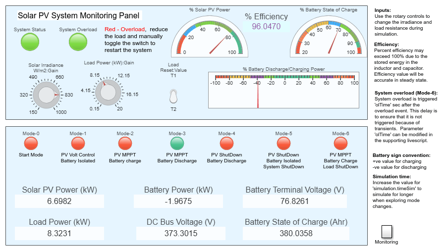
Stand-Alone Solar PV DC Power System Monitoring Panel
This example uses the Simulink Dashboard feature to display all the real time system parameters. Turn the dashboard knob in the monitoring panel to modify the solar irradiance and the load during the simulation. By changing these parameters, you can observe how the PV system switches between the operating modes.
Solar Plant Subsystem
The solar plant subsystem models a solar plant that contains parallel-connected strings of solar panels. The solar panel is modeled using the Solar Cell block from the Simscape Electrical library. To estimate the number of series-connected solar panel strings, this example uses the output voltage from the DC bus and the open-circuit voltage depending on temperature and irradiance. To estimate the number of parallel-connected solar panel strings, this example uses the plant power rating. Connecting multiple panels slows down the simulation because it increases the number of elements in a model. By assuming uniform irradiance and temperature across all the solar panels, the Solar Panel subsystem reduces the number of solar elements by using the controlled current and voltage sources.

Maximum Power Point Tracking
This example implements two MPPT techniques by using variant subsystems. Set the variant variable MPPT to 0 to choose the perturbation and observation MPPT. Set the variable MPPT to 1 to choose incremental conductance.
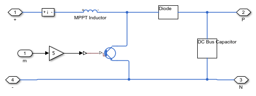
Intermediate Boost DC-DC Converter
This example uses a boost DC-DC converter to control the solar PV power. When the battery is not fully charged, the solar PV plant operates in maximum power point. When the battery is fully charged and the load is less than the PV power, the solar PV operates in constant-output DC bus voltage control mode.
Battery Management System (BMS)
The battery management system uses a bidirectional DC-DC converter. A buck converter configuration and a boost converter configuration charge and discharge the battery, respectively. To improve the battery performance and life cycle, systems with battery backup have limited maximum battery charging and discharging current. This example sets a limit on the maximum amount of power that a battery can supply to the load and absorb from the solar PV source. In this example, the maximum charging power is equal to the solar plant capacity at the standard test condition. This maximum charging power is able to recharge the battery faster than the battery recharge time that you specify.
This example uses a separate controller for the charging and discharging operations. The BMS controller comprises an outer voltage loop and an inner current loop.

Supervisory Control (Mode Control) Parameters
The stand-alone PV system in this example comprises seven operating modes. These modes are selected based on DC bus voltage, solar irradiance, and state of charge of the battery. This example uses the DC bus voltage level as a measure to detect a load imbalance. If the DC bus voltage is greater than  , the system is generating more power than what the load is requiring. If the DC bus voltage is less than
  , then the load is requiring more power than what the system is generating.
The DC bus voltage level  , solar irradiance
  and the battery state of charge
  are used to decide the suitable operating mode.
Operating modes of the stand-alone PV DC System are:
Mode-0 - Start mode (Default simulation starting mode)
Mode-1 - PV in output voltage control, battery fully charged and isolated
Mode-2 - PV in maximum power point, battery is charging
Mode-3 - PV in maximum power point, battery is discharging
Mode-4 - Night mode, PV shutdown, battery is discharging
Mode-5 - Total system shutdown
Mode-6 - PV in maximum power point, battery is charging, load is disconnected
Stateflow mode control diagram

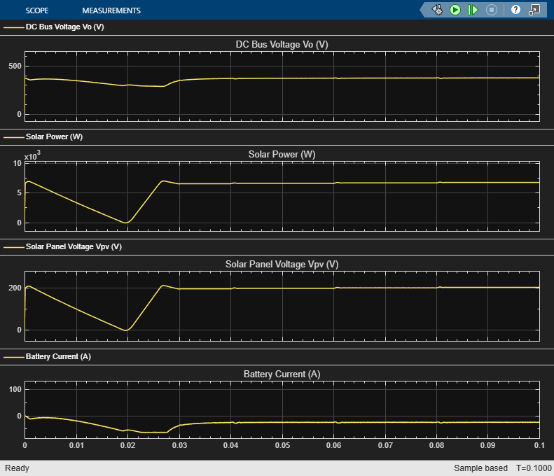
Simulation Output