Group and Execute Transitions
Transition Flow Chart Types
Before executing transitions for an active state or chart, Stateflow® software groups transitions by the following types:
Default flow charts are all default transition segments that start with the same parent.
Inner flow charts are all transition segments that originate on a state and reside entirely within that state.
Outer flow charts are all transition segments that originate on the respective state but reside at least partially outside that state.
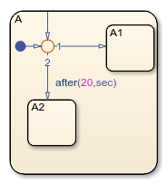
Each set of flow charts includes other transition segments connected to a qualifying transition segment through junctions and transitions. Consider the following example:

In this example, state A has both an inner and a default
transition that connect to a junction with outgoing transitions to states
A.A1 and A.A2. If state A is
active, its set of inner flow charts includes:
The inner transition
The outgoing transitions from the junction to state
A.A1andA.A2
In addition, the set of default flow charts for state A includes:
The default transition to the junction
The two outgoing transitions from the junction to state
A.A1andA.A2
In this case, the two outgoing transition segments from the junction are members of more than one flow chart type.
Order of Execution for a Set of Flow Charts
Each flow chart group executes in the order of group priority until a valid transition appears. The default transition group executes first, followed by the outer transitions group and then the inner transitions group. Each flow chart group executes as follows:
Order the transition segments for the active state.
An active state can have several possible outgoing transitions. The chart orders these transitions before checking them for validity. See Transition Evaluation Order.
Select the next transition segment in the set of ordered transitions.
Test the transition segment for validity.
If the segment is invalid, go to step 2.
If the destination of the transition segment is a state, do the following:
Testing of transition segments stops and a transition path forms by backing up and including the transition segment from each preceding junction back to the starting transition.
The states that are the immediate substates of the parent of the transition path exit (see Exit a State).
The transition action from the final transition segment of the full transition path executes.
The destination state becomes active (see Enter a Chart or State).
If the destination is a junction with no outgoing transition segments, do the following:
Testing stops without any state exits or entries.
If the destination is a junction with outgoing transition segments, repeat step 1 for the set of outgoing segments.
After testing all outgoing transition segments at a junction, take the following actions:
Backtrack the incoming transition segment that brought you to the junction.
Continue at step 2, starting with the next transition segment after the backup segment.
The set of flow charts completes execution when all starting transitions have been tested.