Measure PWM Duty Cycle Using Timer Capture
R2026bThis example shows how to measure the duty cycle of an incoming PWM signal by using the Timer Capture block in STM32® Microcontroller Blockset, with and without DMA support. The example targets a STM32-NucleoH743ZI2 board and uses TIM1 Channel 1 and TIM1 Channel 2 configured in PWM Input mode in STM32CubeMX.
Open the Model
The model (PWMModeTimerCapture) provided with this example contains two functional sections.
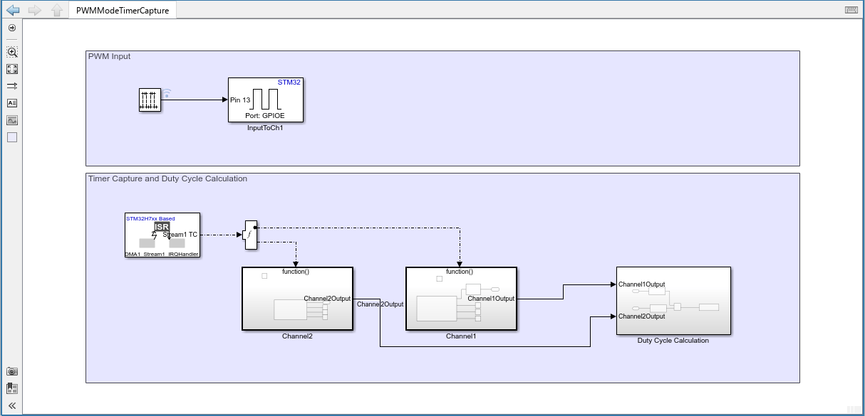
Generate and Route the PWM Input Signal
The PWM input pin routes an external PWM waveform to TIM1 Channel 1. In this example, the model generates a PWM waveform on port GPIOE and pin 13. Short this pin to the pin connected to the TIM1_CH1 input so that TIM1 can capture the waveform.
Capture the PWM Signal and Compute Duty Cycle
The second section in the model reads the timer capture values and computes the duty cycle. It contains these components:
Hardware Interrupt block
This block generates a function-call event when the selected interrupt occurs. Configure the block to use:
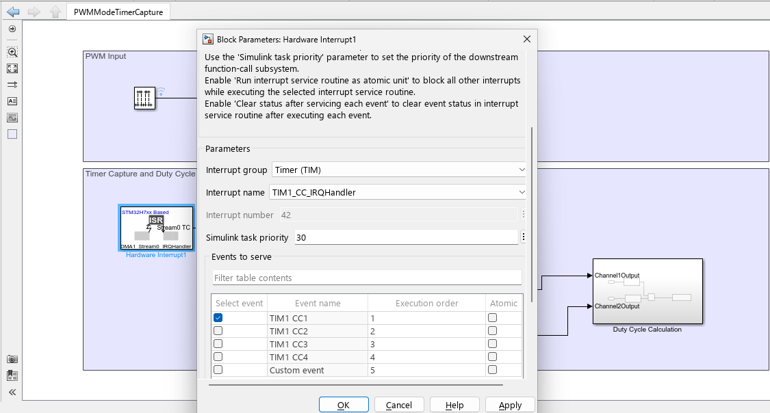
TIM1 Capture Compare (CC) interrupt in non-DMA mode.
DMA Transfer Complete interrupt in DMA mode.
Channel 2 Timer Capture
This subsystem reads the captured period value, which corresponds to the time between consecutive rising edges.
Channel 1 Timer Capture
This subsystem reads the captured high-time value. The block can operate in either Normal mode (which returns a single capture value) or in DMA mode (which returns an array of captured values).
Duty Cycle Calculation
This subsystem computes the duty cycle from the captured period and high-time measurements.
Timer Configuration
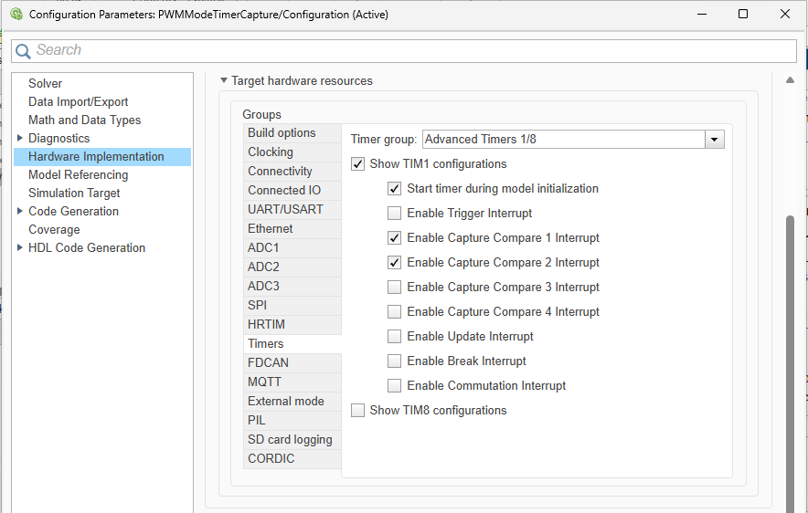
Ensure that the interrupt for the capture compare event is configured in Simulink Configuration Parameters. Go to Hardware Implementation > Target hardware resources > Timers, and select Show TIM1 configurations.
Additionally, to start the timer counter for TIM1 during model initialization, select Start timer during model initialization. Alternatively, to start the timer counter in runtime, add a Timer block, and select Timer Module as TIM1 and select the Enable timer counter period input parameter. An input of 1 starts the counter and input of 0 stops the counter in runtime.
Use DMA to Improve Measurement Stability
When DMA is enabled for TIM1 Channel 1, the Timer Capture block returns an array of captured values instead of a single measurement. Configure the number of captured samples by setting the Capture data length parameter in the Timer Capture block.
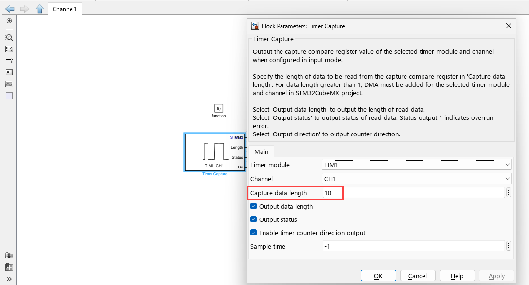
The DMA transfer-complete interrupt occurs after the block collects the specified number of samples.
The DMA array size determines how many measurements are available before the model updates the duty cycle calculation. In this example:
The PWM period is 0.1 s.
Each captured sample corresponds to one PWM cycle.
The DMA capture length is set to 10 samples.
To reduce measurement noise caused by switching edges and input jitter, the model averages the captured values before calculating the duty cycle.
Increasing the capture length can improve noise suppression but reduces the update rate of the measurement.
Configure the Hardware Interrupt block to use:
Interrupt Group: DMA
Interrupt Name: DMA Stream 1
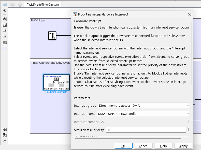
These settings must match the DMA configuration for TIM1_CH1 in STM32CubeMX.
Configure TIM1 in STM32CubeMX
Configure TIM1 in Combined Channel PWM Input mode.
For DMA operation, add a DMA request for TIM1_CH1 with these settings:
Direction: Peripheral to Memory
Stream: DMA Stream 1
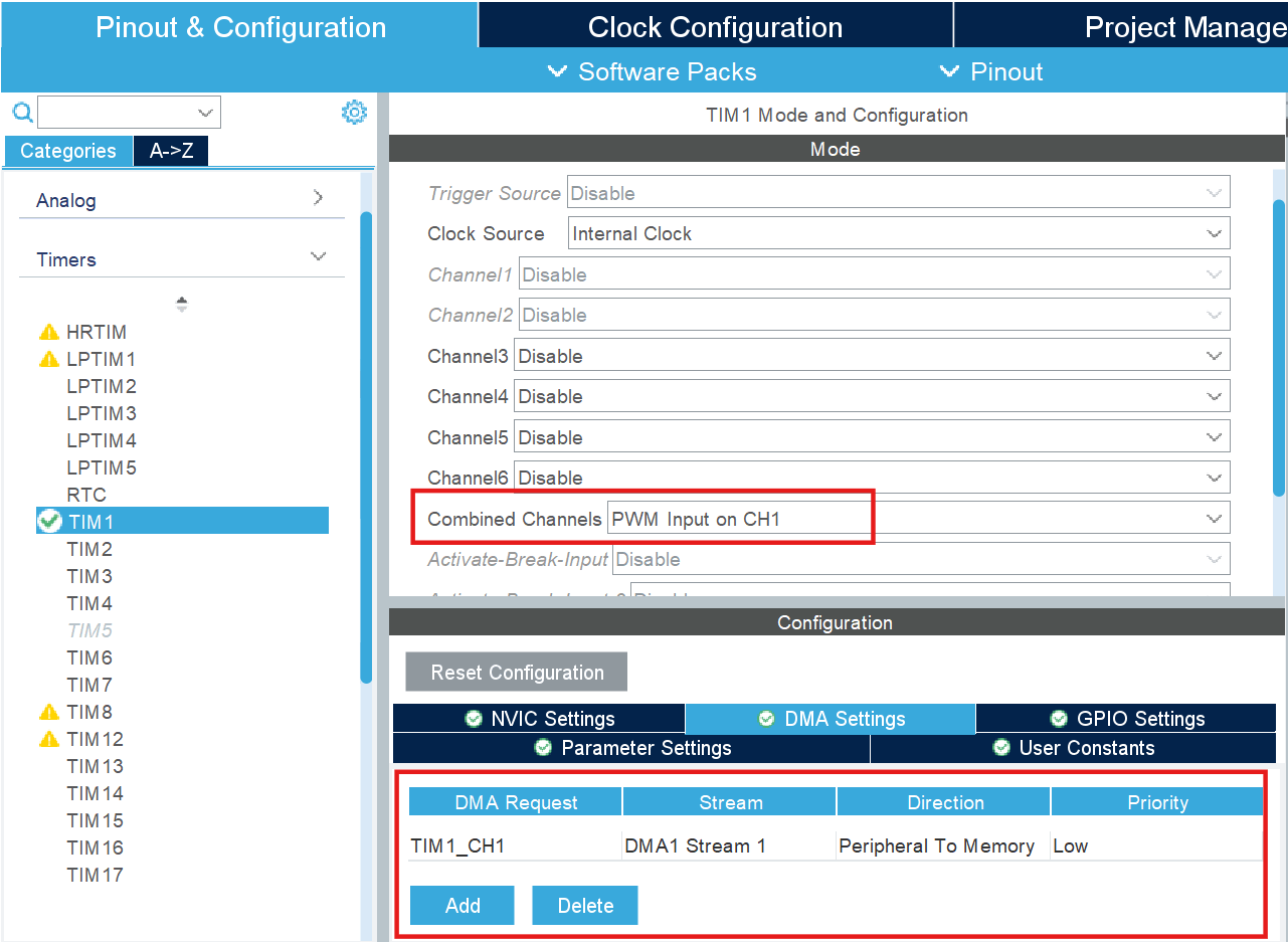
Select the same DMA stream in the Hardware Interrupt block in the Simulink model.
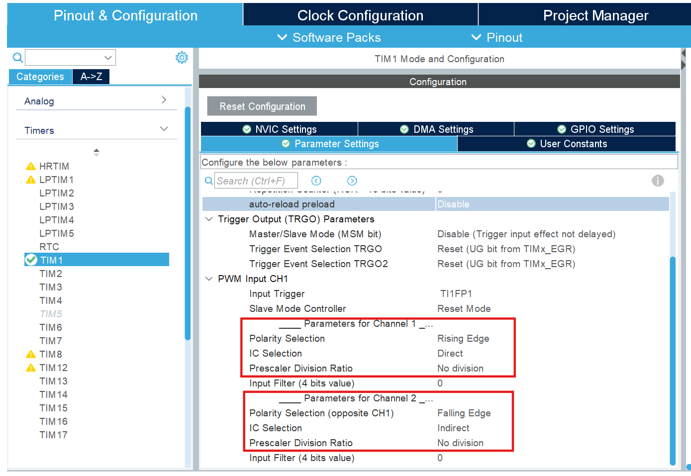
Configure TIM1 Channel 1 and Channel 2 in PWM Input mode to capture the timing characteristics of the incoming PWM signal. Configure the Slave Mode Controller to use Reset Mode, which resets the timer counter to zero on every rising edge of the input signal. In this configuration, Channel 1 captures the time between consecutive rising edges and therefore represents the signal period. Channel 2 captures the timer value at the falling edge and therefore represents the signal high time. The model uses these capture values to calculate the PWM duty cycle.
Run the Model Without DMA
In non-DMA mode, the Timer Capture block outputs a single capture value instead of an array.
Set the Capture data length parameter of the Timer Capture block to 1.
Configure the Hardware Interrupt block to use the TIM1 Capture Compare (CC) interrupt.
Calculate the Duty Cycle
The model computes the PWM duty cycle by using the captured values from TIM1 Channel 1 and TIM1 Channel 2.
Each capture value represents a timer count. Convert the capture counts to time by using the timer prescaler value and timer clock frequency.
You can view and modify these settings in the STM32CubeMX .ioc files provided with this example.
Use the Channel 1 capture value to calculate the signal period.
Use the Channel 2 capture value to calculate the signal high time ().
Calculate the duty cycle as:
In this example:
Prescaler = 10,000
Timer clock frequency = 100 MHz
Therefore:
When you simulate the model, you can observe the captured values and the computed duty cycle in the Simulation Data Inspector.
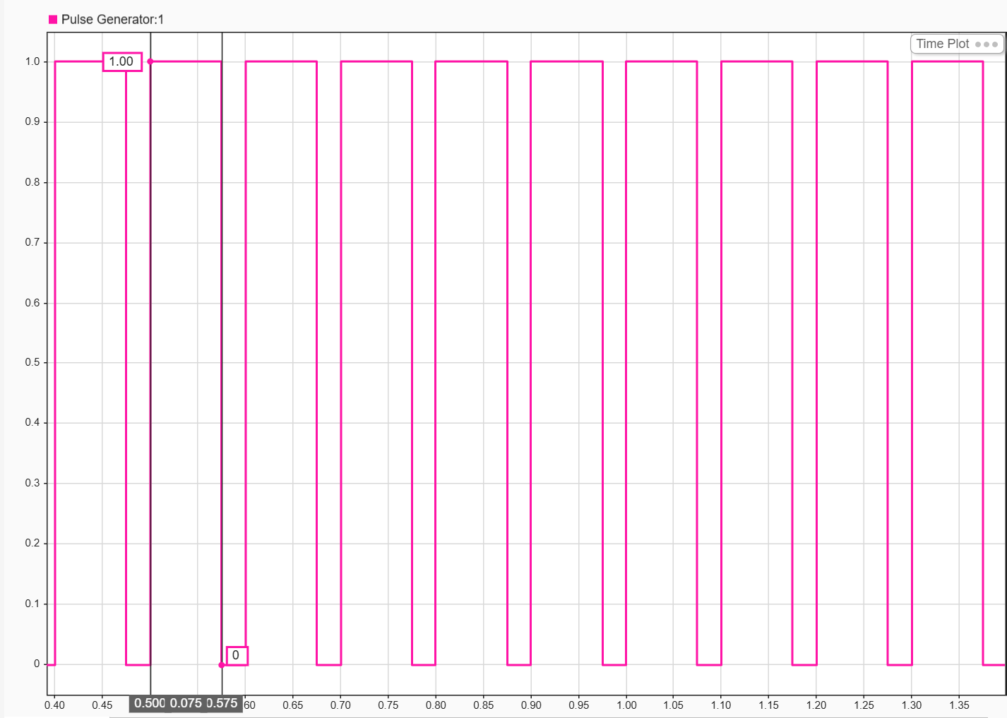
Input PWM Waveform
The PWM pulse generated on the GPIO pin, used as the input stimulus for the timer capture measurement. The signal alternates between 0 and 1 with the configured duty cycle.
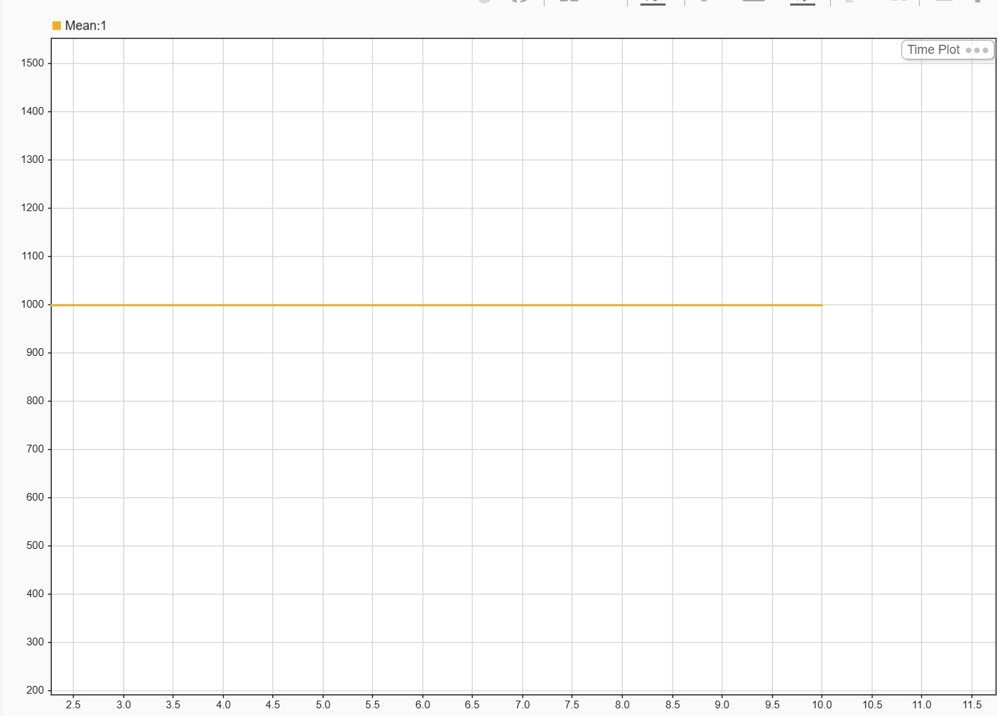
Timer Capture Value from TIM1 Channel 1
The Timer capture value from TIM1 Channel 1 (rising edge to rising edge), represents the period of the incoming PWM signal. The measured value of 1000 ticks corresponds to a period of 0.1 seconds.
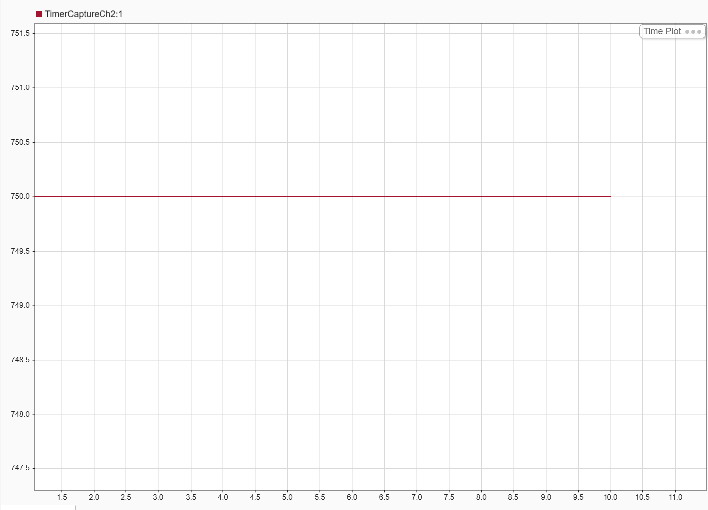
Timer Capture Value from TIM1 Channel 2
The Timer capture value from TIM1 Channel 2 (rising edge to falling edge), representing the on-time (T_on) of the PWM signal. The measured value of 750 ticks corresponds to a high-time of 0.075 seconds.
Computed Duty Cycle
Computed duty cycle, calculated as the ratio of Channel 2 () to Channel 1 (Period). The steady-state value of 0.75 confirms the expected 75% duty cycle of the input PWM signal.

