Author Quality of Service Properties Using Software Component Designer
R2026bWhen designing service-oriented software, you can define communication and execution behavior at the architecture level before implementing component algorithms. This architecture-first approach lets you:
Capture behavioral intent — buffering semantics, execution triggering, error handling — independently of Simulink® implementation
Generate template Simulink software component models that already reflect your quality of service (QoS) decisions
Iterate on communication and execution design without modifying component implementations
If you already have Simulink software component models and want to configure QoS properties within them, see Configure Communication and Execution Behavior of Software Components.
Note
This workflow requires the Software Component Designer for Simulink support package, which provides the authoring and simulation capabilities for software architecture models with QoS properties.
Create Software Architecture Model
Use a software architecture model as the starting point for behavior definition. The architecture model provides the context in which you define component interactions, communication and execution semantics, and error handling for software components.
To create a software architecture model, from a Simulink model, on the Simulation tab, select New > Architecture
 .
.
System Composer™ opens a new empty software architecture model. For more information, see Author Software Architectures.
Define Component Interfaces
Define interfaces to specify the interaction between software components. Interfaces describe the data and services that component exchange independently of component implementation.
You can use the Interface Editor to create or link Simulink data dictionaries to your architecture model. Use data interfaces to define send-receive interactions and service interfaces to define client-server interactions.
To open the Interface Editor, from the toolstrip, on the Software Component tab, click Interface Editor .
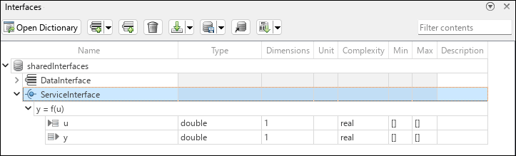
Assign interfaces to component ports to expose interface elements and enable behavior definition. When you assign an interface to a port, the interface elements appear in the Property Inspector as data elements or function elements. These elements form the basis for defining communication and execution behavior using QoS properties.
Assign data interfaces to input and output ports to enable send-receive communication.
Assign service interfaces to client and server ports to enable client-server communication.
Define Communication and Execution Behavior Using QoS Properties
QoS properties define how software components communicate and execute at run-time. When you specify QoS properties in a software architecture model, you describe observable communication behavior independently of component algorithms.
You can specify QoS properties on port elements to define semantics such as buffering behavior, data availability, request-response timing, and execution blocking. The architecture preserves these semantics when it generates template software component models.
To enable configuration of communication and execution behavior, open the
Software Component Designer app. From the apps gallery, in the Code
Generation section, click Software Component
Designer
 .
.
Configure Send-Receive Communication
Send‑receive communication defines how data flows from sender components to receiver components. QoS properties for send‑receive communication define how the system buffers data and how receivers access transmitted data values.
To configure communication and execution properties, from the Property Inspector, on the Parameters tab, select a data element.
For input port data elements, on the Service tab, in the Communication section, set these properties.
Receiver service – Selects how the receiver accesses buffered data. Set to
Queuedto read values from a queue. Set toLatestValueto read only the most recent value.Queue capacity – Sets the maximum number of values stored in the queue, with a default value of
16.Initial value – Defines the value used by the receiver before it receives the first valid value from the sender, with a default value of
0.Status element – Optional element that enables run-time reporting of data access status.
Timeout – Specifies maximum time allowed since valid data was last received by the port, with a default value of
Inf. Set to a finite value to enable timeout monitoring.
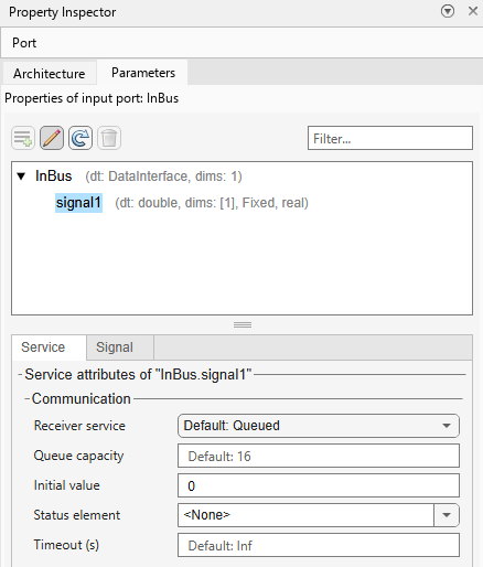
For output port data elements, configure sender properties so they align with receiver expectations. On the Service tab, in the Communication section of the Property Inspector, set Sender service to one of these values:
Queued– The sender queues data and delivers values in the order sent.LatestValue– The sender retains only the most recent data value.
Configure Client-Server Communication
Client-server communication defines how one component invokes a function that another component provides. QoS properties for client-server communication define request-response semantics and execution behavior.
Each function element of a client or server port represents a function provided or requested by a component.
To configure communication and execution properties, from the Property Inspector, on the Parameters tab, select a function element.
In the Property Inspector, on the Service tab, in the Communication section, set properties that control whether the client can request a response from the server and how middleware responses are handled.
Timeout – Specifies maximum time allowed between when the client invokes a function and receives results, with a default value of
Inf. Set to a finite value to enable timeout monitoring.Server response not required – Specifies whether the client requires a response from the server, with a default value of
off.The Server response not required property can be selected only for function elements whose function prototype defines no output arguments. When this property is selected, the Caller behavior execution property is read-only and ignored by the software as the client does not receive a response from the server. To clear the Server response not required property, select the function element in the Interface Editor, and then edit its properties in the Property Inspector.
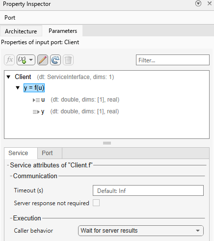
In the Execution section, set Caller behavior to define how the client proceeds while waiting for results.
Wait for server results– The client blocks execution until results become available within the same step, which requires the Timeout value to be less than or equal to the step size.Allow delayed server results– The client continues execution and polls for results across multiple steps, up to the configured Timeout duration.
Author Component Functions and Configure Data-Triggered Execution
You can specify when and how a component executes at run-time by defining component functions. A component function is an entry point that can be defined in a software component. You can author functions from the architecture level using the Functions Editor.
To open the Functions Editor, from the toolstrip, on the Modeling tab, in the Design section, select Functions Editor.
To create a component function:
Select a component on the canvas.
Click the Add a function button.
You can change the name and period, or sample time, of the function from the table of the Functions Editor.
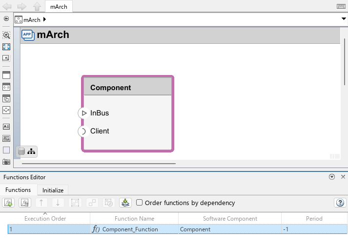
Once you define component functions, you can configure data-triggered execution of a component.
Select an input port on the canvas.
From the Property Inspector, select a data element.
In the Execution section, set the On data arrival, execute parameter to the newly created function.
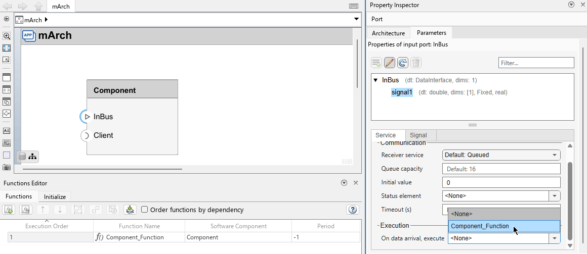
The configured execution behavior you defined is reflected in the generated template software component model. You can then implement the function algorithm within the Simulink software component model.
Define Communication Status and Error Handling
To specify how components report and handle communication outcomes, you can
define communication status and error behavior. You can use the predefined
enumerated data type SlSignalStatus, which provides
platform-independent error codes for communication outcomes, such as successful
execution, timeouts, and general communication errors.
Send-receive communication — Associate each input port data element with a status element to report whether data was received successfully.
Client-server communication — Include an optional
statusargument in a function element prototype to report whether the function call completed successfully.
For detailed steps on adding status arguments and configuring error-handling behavior within software component models, see Configure Communication and Execution Behavior of Software Components.
Implement Component Behavior Using Simulink
Once you define interfaces and quality of service (QoS) properties, you can generate template Simulink software component models for each component of your architecture.
When you create Simulink behavior models directly from an architecture, System Composer provides you with preconfigured models.
If a port has no assigned interface but is connected to a port that does, System Composer propagates the connected interface to the port before creating the model.
To create and link a Simulink model:
Select a component on the canvas. On the toolstrip, click Modeling > Component > Create Simulink Behavior.
In the Create Simulink behavior dialog box, set the Type parameter to
Model Reference: Rate-BasedorModel Reference: Export-Function.Note
If a component has server ports or is configured for data-triggered execution, the linked behavior model must be an export-function model. In this case, set the Type parameter to
Model Reference: Export-Function.Click OK.
Alternatively, you can use the createSimulinkBehavior
function to create and link a behavior model programmatically.
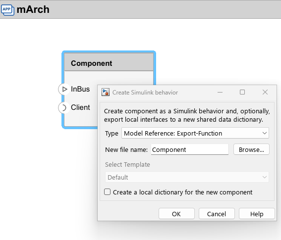
The Simulink icon on the component indicates that it is now linked to a Simulink model.
The created Simulink model is configured as a software component. All interfaces and QoS properties defined on the architecture component — including communication properties and execution properties such as data-triggered execution — are carried over to the created model. Double-click the component to open its model.
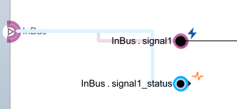
Each data element of an input or output port is represented by a bus element block.
Each status element is also represented by a bus element block and displayed with a status icon
 .
.
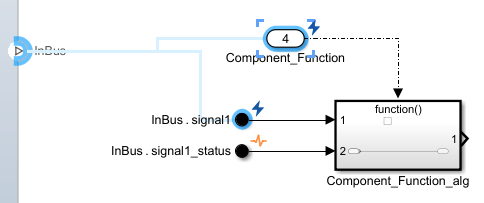
Each component function is represented by a Function-Call Subsystem block named
'<component
                                function>_alg'
. This subsystem is connected to an Inport block that is configured to produce a function-call event.The Inport block and its associated data element are displayed with a trigger icon
 .
.
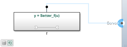
Each function element of a server port is represented by a Simulink Function block.
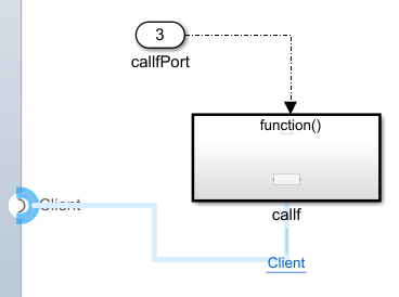
Each function element of a client port is represented by a Function-Call Subsystem block.
If a port has no assigned interface and is not connected to a port with an interface, the created model generates default blocks: a Function-Call Subsystem block for a client port, a Simulink Function block for a server port, or a bus element block for a data port.
Finish implementing behavior of your component by adding any necessary blocks from the Simulink library.
Remove Component Behavior and Preserve Quality of Service Properties
If you need to redesign the algorithm of a software component without losing the communication and execution behavior you defined at the architecture level, you can inline the component. Inlining removes the linked Simulink model reference while preserving all quality of service (QoS) properties on port elements.
Use this workflow to replace the behavior of a component — for example, to author a new implementation using Create Simulink Behavior — without manually re-configuring QoS properties.
To inline a reference component, select the component on the architecture
canvas and, on the toolstrip, click Modeling > Component > Inline Linked Model, or use the inlineComponent function. For more information, see Remove Architecture Reference.
After inlining, the Simulink model reference is removed and the component becomes an inline component. All communication and execution properties that you configured on port elements — such as sender and receiver services, queue capacities, and data-triggered execution — are preserved on the inline component.

