Run ArduPilot Software-in-the-Loop Simulation with Quadcopter Plant in Simulink
This example shows you how to verify a quadcopter controller design by using Software-in-the-Loop (SITL) simulation and to simulate the quadcopter plant model in Simulink using the UAV Toolbox Support Package for ArduPilot® Autopilots.
Prerequisites
1. If you are new to Simulink, watch the Simulink Quick Start video.
2. You must install Mission Planner to create and upload a UAV mission used in this example.
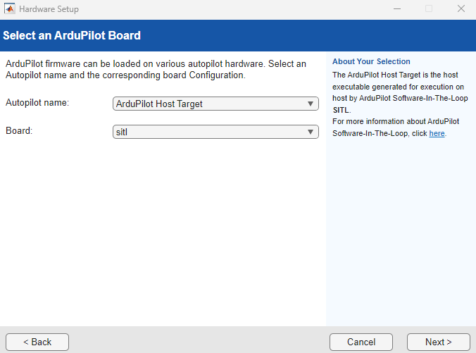
3. If you have not done so already, complete the steps in Install UAV Toolbox Support Package for ArduPilot Autopilots in Windows. At the Select an ArduPilot Board step of installation, specify these options:
Autopilot name — ArduPilot Host Target
Board — sitl
4. You must start two instances of MATLAB® to run this example. Use the first instance of MATLAB to deploy the quadcopter controller model to the ArduPilot host target. Use the second instance of MATLAB to run the quadcopter plant model.
Getting Started in First MATLAB Instance
Launch the first instance of MATLAB. To access the Simulink model, supporting files, and project shortcuts that this example uses, open the ArduPilotSITLSimulinkPlant.prj project file.
prj = openProject("ArduPilotSITLSimulinkPlant");Copy the current folder path of the first MATLAB instance to the clipboard.
clipboard("copy", pwd)Quadcopter Dynamics Model Overview
To open the quadcopter Quad_UAV_Dynamics.slx Simulink model, on the Project tab of the MATLAB Toolstrip, in the Shortcuts section, click the Step 1: Run Quadcopter Dynamics Simulation shortcut.
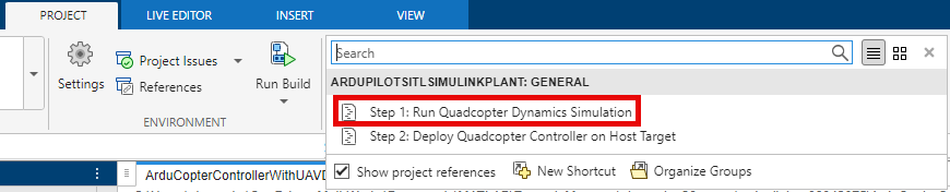
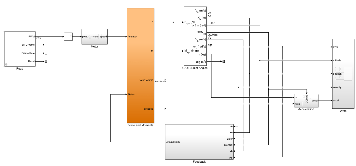
The Quad_UAV_Dynamics.slx Simulink model contains these main blocks and subsystems:
Readsubsystem — Reads the PWM signals sent by the ArduPilot host target through a UDP connection.Motorsubsystem — Converts the PWM signals to motor angular velocity.Force and Momentssubsystem — Calculates the forces and moments that are generated by the aerodynamic, propulsion system, gravity, and ground contact models based on the motor angular velocity and quadcopter states, which it passes to the 6DOF (Euler Angles) block as inputs.6DOF (Euler Angles) (Aerospace Blockset) block — Calculates the quadcopter states based by using six-degrees-of-freedom equations of motion.
Writesubsystem — Sends the quadcopter states to the ArduPilot host target through a UDP connection.
Run Quadcopter Plant Model in First MATLAB Instance
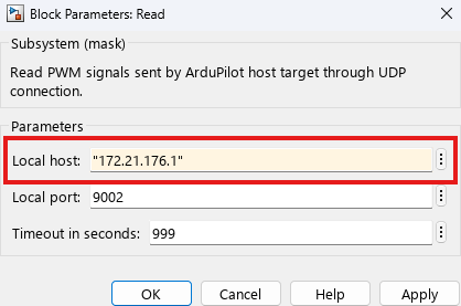
Obtain the Windows host’s IP address on the virtual network used by Windows Subsystem for Linux (WSL), which is running the ArduPilot flight stack. To find this IP address, open the Windows Command Prompt and run ipconfig. In the example image, the host’s IP address on the WSL network is shown as 172.21.176.1.
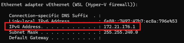
In the Quad_UAV_Dynamics.slx model, open the block mask of the Read subsystem. Specify the Local host parameter as the WSL IP address, and specify the Local port parameter as 9002. Click OK to save the changes.
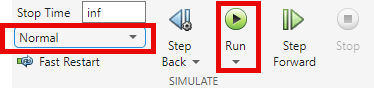
On the Simulation tab of the Simulink Toolstrip, in the Simulate section , select the Normal simulation mode, then click Run ![]() to start the
to start the Quad_UAV_Dynamics.slx model.
For more information on connecting MATLAB to ArduPilot SITL, see the MATLAB Simulation section of the ArduPilot documentation.
Getting Started in Second MATLAB Instance
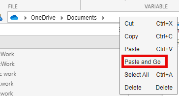
Launch a second instance of MATLAB. Then, right-click the current working directory in the address bar and paste the folder path of the first instance of MATLAB by selecting Paste and Go.
To access the Simulink model, supporting files, and project shortcuts that this example uses, open the ArduPilotSITLSimulinkPlant.prj project file.
prj = openProject("ArduPilotSITLSimulinkPlant");Quadcopter Controller Model Overview
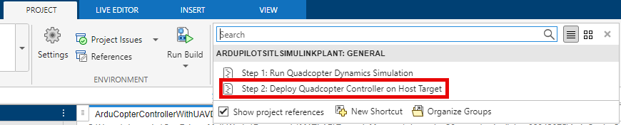
To open the Quadcopter_Controller.slx Simulink model, on the Project tab of the MATLAB Toolstrip, in the Shortcuts section, click the Step 2: Deploy Quadcopter Controller on Host Target shortcut.
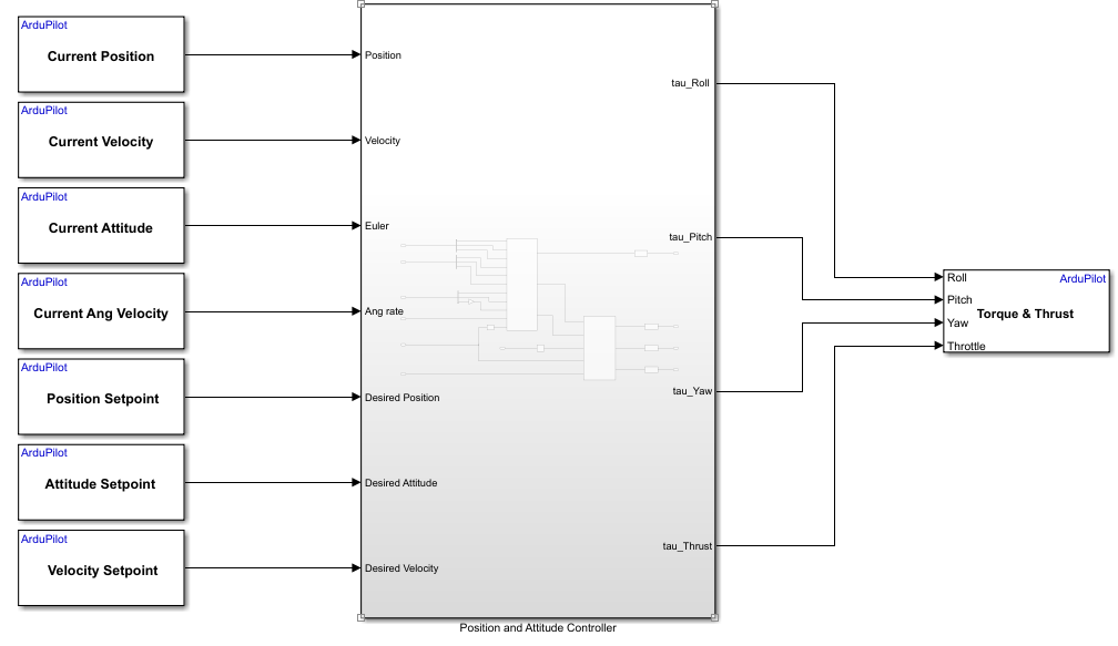
The Position and Attitude Controller subsystem calculates the normalized thrust, yaw, pitch, and roll commands, which it passes to the Write Torque & Thrust block as inputs. The Write Torque & Thrust block writes the normalized thrust, yaw, pitch, and roll commands to the ArduPilot motor mixer.
The Position and Attitude Controller subsystem obtains the setpoints by using these blocks:
Position Setpoint — Outputs the position setpoint set by the ArduPilot guidance system based on the current flight mode. When the quadcopter is in the
Missionflight mode, the block outputs the position target that guides the UAV to navigate all of the mission waypoints.Velocity Setpoint — Outputs the velocity setpoint set by the ArduPilot guidance system based on the current flight mode.
Attitude Setpoint — Outputs the attitude setpoint set by the ArduPilot position controller.
The Position and Attitude Controller subsystem obtains the position, velocity, attitude, and angular velocity feedback that the ArduPilot attitude heading reference system (AHRS) estimates by using these blocks:
Current Position — Outputs the current UAV position.
Current Velocity — Outputs the current UAV velocity.
Current Attitude — Outputs the current attitude of the UAV.
Current Ang Velocity — Outputs the current angular velocity of the UAV.
For more details on how to design a position and attitude controller for ArduPilot autopilots, see the Design Quadrotor Position and Attitude Controllers for ArduCopter example.
For more details on ArduPilot position control and waypoint navigation, see the Copter Position Control and Navigation section of the ArduCopter documentation.
Verify Hardware Settings
On the Simulink Toolstrip of the Quadcopter_Controller.slx model, on the Hardware tab, click Hardware Settings ![]() . In the left pane, select Hardware Implementations, and verify these options:
. In the left pane, select Hardware Implementations, and verify these options:
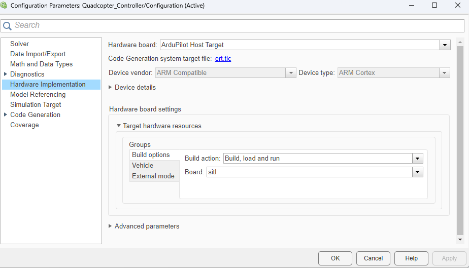
Hardware board is set to
ArduPilot Host Target.In the Hardware board settings section, under Target hardware resources, select the Build options tab of the Groups pane. Note that Build action is set to
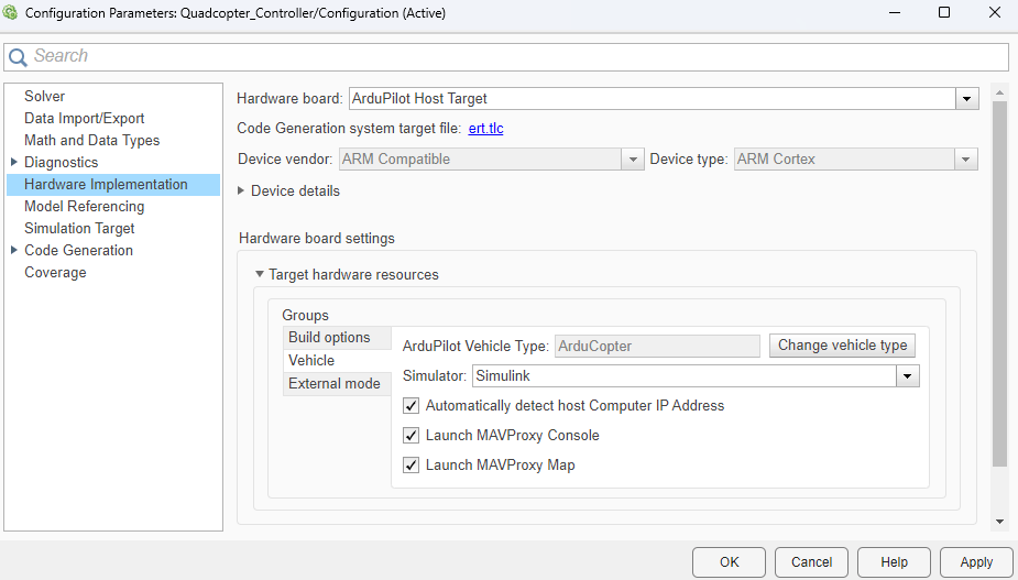
Build, load and run, and Board is set tositl.Select the Vehicle tab of the Groups pane. Verify that Simulator is set to
Simulink.
Click OK to save any changes and close the Configuration Parameters dialog box.
Run Quadcopter Controller Model in Second MATLAB Instance
To run the Quadcopter_Controller.slx model in Monitor & Tune mode:
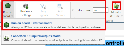
1. From the Simulink Toolstrip, select the Hardware tab.
2. Verify that the Mode section contains a Run on board button. If it instead contains a Connected IO button, click Connected IO, then Run on board (External mode).
3. In the Run on Hardware section, click Monitor & Tune ![]() .
.
Create and Upload Mission in Mission Planner
After you run both the Quad_UAV_Dynamics.slx and Quadcopter_Controller.slx models, MAVProxy launches automatically. After MAVProxy starts, open Mission Planner. The Mission Planner automatically connects to the quadcopter through UDP port 14550. If the Mission Planner does not connect, create a manual UDP connection using port 14550.
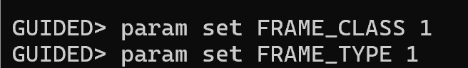
In the MAVProxy command window, enter the commands param set FRAME_CLASS 1 and param set FRAME_TYPE 1 to set the FRAME_CLASS to quadcopter and FRAME_TYPE to 'X'.
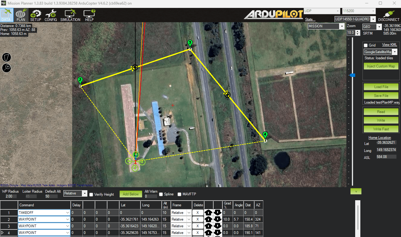
Open the Flight Planner menu in Mission Planner by clicking Plan.

Load or create a new flight plan. For more information on how to plan missions in Mission Planner, see Planning a Mission with Waypoints and Events in the ArduPilot documentation.
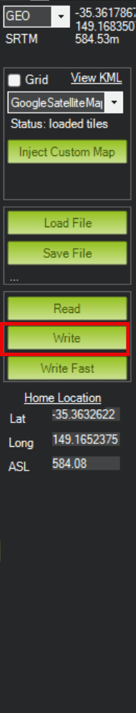
Once you have created your mission, click Write to upload the flight plan to the quadcopter.
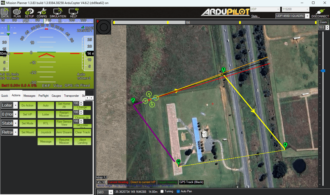
Return to Flight Data menu by clicking the Data button.

Start Mission
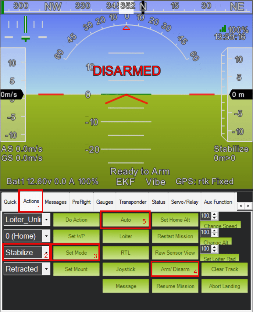
To start the mission from the Flight Data menu:
Select the Actions tab.
Select
Stabilizefrom the mode drop-down.Select Set Mode.
Select Arm/ Disarm to arm the quadcopter.
Select Auto.
The quadcopter now flies through the mission using the deployed controller and plant models from Simulink.
To end the simulation after the mission has finished, first stop the Quad_UAV_Dynamics.slx Simulink model, then stop the Quadcopter_Controller.slx Simulink model. If you instead stop the Quadcopter_Controller.slx Simulink model first, then you need to press Ctrl+C to stop the Quad_UAV_Dynamics.slx Simulink model.