Add GPS Sensor Noise to Multirotor Guidance Model
This example shows how to use a gpsSensor Block to add sensor noise to the position and velocity output of a guidance model in Simulink®.
Example Model
Open the Simulink model.
open_system("uavGPSModel.slx");
The model uses a Guidance Model block to simulate a multirotor UAV platform. The GPS block adds noise to the state of the UAV.
Constant values for the roll, pitch, and yaw rate, and a varying value created by a sine wave for the thrust are inputs to Control port of the Guidance Model. The roll, pitch and yaw rate are set to 0 so the varying thrust input changes only the height. When setting the controls for the block, check that the gain values listed in the block are appropriate. The only Environment input for a multirotor UAV is gravity, specified as 9.81. Bus Creator (Simulink) blocks combine the control inputs and environment input into their respective busses, with the bus names specified in the Input/Output Bus Names parameter of the Guidance Model.
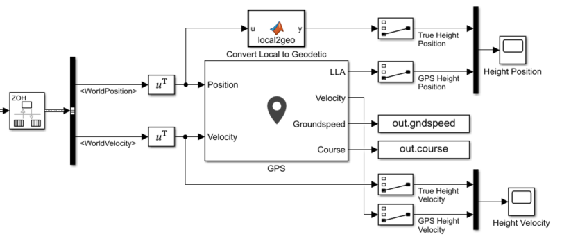
Because the GPS block uses discrete states and has separate inputs for Position and Velocity, the model uses a Rate Transition block to convert the continuous signal from the Guidance Model block into a bus containing two discrete signals. It extracts the WorldPosition and WorldVelocity signals from the bus and transposes them before using them as input to the GPS block. Scope blocks display the true vertical position and vertical velocity of the UAV alongside its GPS-affected vertical position and vertical velocity readings.
Run the Model
Run the model. The Height Position and Height Velocity scopes show the effect the GPS block has on the original values of the position and velocity signals, retrospectively.
