WLAN LDPC Decoder
Libraries:
Wireless HDL Toolbox /
Error Detection and Correction
Description
The WLAN LDPC Decoder block implements a low-density parity-check (LDPC) decoder using a layered belief propagation with min-sum approximation and normalized min-sum approximation algorithms for decoding LDPC codes according to the wireless local area network (WLAN) standards IEEE® 802.11n™, 802.11ac™, 802.11ax™, and 802.11ad™. The block accepts log-likelihood ratio (LLR) values, a stream of control signals, a block length, and a code rate as inputs and outputs decoded bits, a stream of control signals, and a signal that indicates when the block is ready to accept new inputs.
The WLAN LPDC Decoder block supports scalar inputs and vector inputs. The block supports early termination to help improve decoding performance and convergence speeds at high signal-noise-ratio (SNR) conditions. For more information about WLAN standards, see [1], [2], and [3].
The block provides an architecture suitable for HDL code generation and hardware deployment. You can use this block in the WLAN modem development.
Examples
Decode WLAN LDPC Streaming Data
Simulate WLAN LDPC Decoder block and compare hardware-optimized results with results from Communication Toolbox™ function.
Ports
Input
Output
Parameters
Algorithms
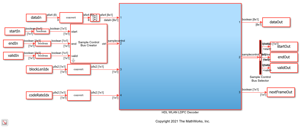
This figure shows the architecture block diagram of the WLAN LDPC Decoder block. The Controller block controls the layer and iteration count of the decoding process. The Variable node RAM block stores the variable node (VN) messages, and the Check node RAM block stores the check node (CN) messages. The Functional Unit block calculates the VN messages and CN messages based on the layered belief propagation and either the normalized min-sum approximation algorithm or the min-sum approximation algorithm. The Termination/Parity check status block calculates the parity checks and provides the parity check status after each iteration. For more information about decoding algorithms, see the following sections.

The latency of the block varies based on the selected Standard parameter, the values of the blkLenIdx and codeRateIdx input ports, and the number of iterations. Because the latency varies, use the nextFrame control signal output port to determine when the block is ready for a new input frame.
The latency of the block is equal to r x (t +
m x 9) + d. In this calculation, r is the number of iterations,
t is twice the total number of non –1 elements in the PCM,
m is the number of rows in the PCM, and d is the
pipeline delays. For scalar inputs, d is 13.
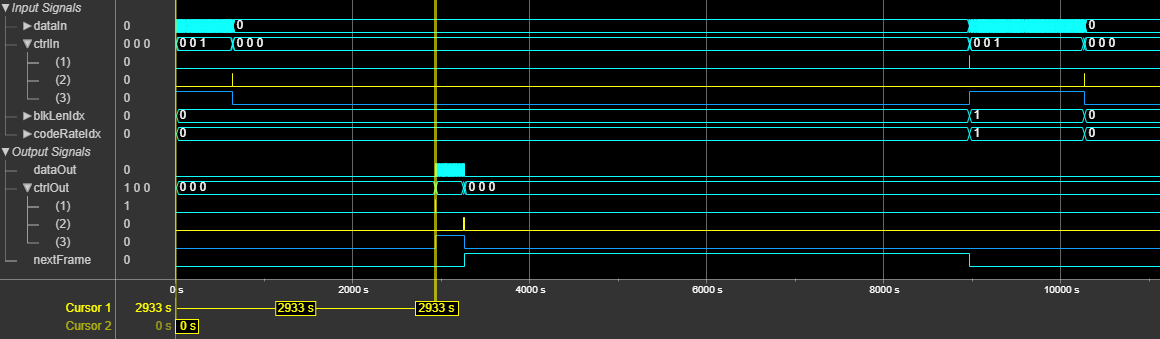
This figure shows a sample output and latency of the WLAN LDPC Decoder
block for a scalar input when you set the Standard parameter to
IEEE 802.11 n/ac/ax, the Algorithm parameter to
Min-sum, the Number of iterations parameter to
8 and the blkLenIdx and the
codeRateIdx input port values both to 0 and
0. The latency of the block is 2933 clock cycles.
The latency of the block is equal to r x (t +
m x 9) + d. In this calculation, r is number of iterations,
t is twice the total number of non –1 elements in the PCM,
m is the number of rows in the parity check matrix, and
d is the pipeline delays. For vector inputs, when you set the
Standard parameter to:
IEEE 802.11 n/ac/ax, d is 35, 32, and 35 for blkLenIdx input port values0,1, and2, respectivelyIEEE 802.11 ad, d is 26
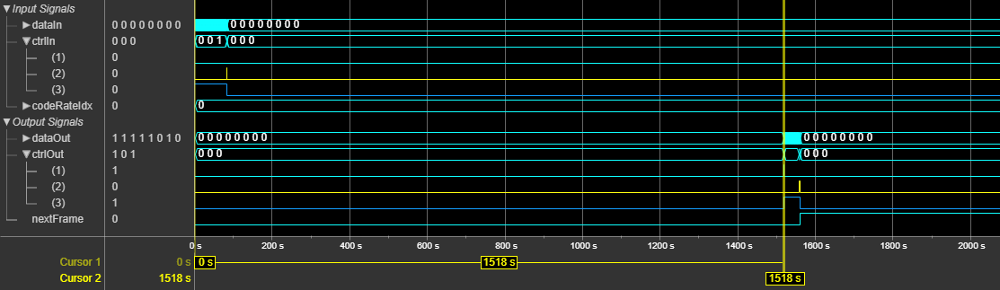
This figure shows a sample output and latency of the WLAN LDPC Decoder
block for a vector input when you set the Standard parameter to
IEEE 802.11
              ad
, the Algorithm parameter to
Normalized
          min-sum
, the Number of iterations
parameter to 8, and the codeRateIdx input port
value to 0. The latency of the block is 1518 clock cycles.
This section shows the SNR and BER plots of the block for specified inputs and parameter settings.
This plot shows the performance of the block for a 4 bit QPSK-modulated LLR input, when
you set the Standard parameter to IEEE 802.11
n/ac/ax, the Algorithm parameter to
Min-sum, the blkLenIdx input port value to
0 (block length of 648) and the codeRateIdx input
port value to 0, 1, 2, and
3 (code rates of 1/2, 2/3, 3/4, and 5/6, respectively).

This plot shows the performance of the block for a 4 bit QPSK-modulated LLR input, when
you set the Standard parameter to IEEE 802.11
ad, the Algorithm parameter to Normalized
min-sum, and the codeRateIdx input port value to
0, 1, 2, and 3
(code rates of 1/2, 5/8, 3/4, and 13/16, respectively). In this case, the block length is
fixed to 672.

References
[1] IEEE Std 802.11™-2016 (Revision of IEEE Std 802.11-2012). “Part 11: Wireless LAN Medium Access Control (MAC) and Physical Layer (PHY) Specifications.” IEEE Standard for Information technology — Telecommunications and information exchange between systems. Local and metropolitan area networks — Specific requirements.
[2] IEEE STD 802.11ad-2012 (Amendment to IEEE Std 802.11-2012, as amended by IEEE Std 802.11ae™-2012 and IEEE Std 802.11a™-2012). “Part 11: Wireless LAN Medium Access Control (MAC) and Physical Layer (PHY) Specifications. Amendment 4: Enhancements for Very High Throughput Operation in Bands below 6 GHz.” IEEE Standard for Information technology — Telecommunications and information exchange between systems. Local and metropolitan area networks — Specific requirements.
[3] IEEE Std 802.11ah™-2016 (Amendment to IEEE Std 802.11-2016 as amended by IEEE Std 802.11ai™-2016). “Part 11: Wireless LAN Medium Access Control (MAC) and Physical Layer (PHY) Specifications. Amendment 2: Sub 1 GHz License Exempt Operation.” IEEE Standard for Information technology — Telecommunications and information exchange between systems. Local and metropolitan area networks — Specific requirements.
[4] Gallager, R. “Low-Density Parity-Check Codes.” IEEE Transactions on Information Theory 8, no. 1 (January 1962): 21–28. https://doi.org/10.1109/TIT.1962.1057683.
[5] Hocevar, D.E. “A Reduced Complexity Decoder Architecture via Layered Decoding of LDPC Codes.” In IEEE Workshop OnSignal Processing Systems, 2004. SIPS 2004., 107–12. Austin, Texas, USA: IEEE, 2004. https://doi.org/10.1109/SIPS.2004.1363033.
[6] Chen, Jinghu, R.M. Tanner, C. Jones, and Yan Li. "Improved min-sum decoding algorithms for irregular LDPC codes." In Proceedings. International Symposium on Information Theory, 2005. ISIT 2005. https://doi: 10.1109/ISIT.2005.1523374.
Extended Capabilities
Version History
Introduced in R2021b