802.11ad Packet Error Rate Simulation for Control PHY
This example shows how to measure the packet error rate of an IEEE® 802.11ad™ DMG control PHY AWGN link using an end-to-end simulation.
Introduction
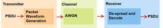
In this example an end-to-end simulation is used to determine the packet error rate for an 802.11ad [ 1 ] control PHY link with an AWGN channel at a selection of SNR points. At each SNR point multiple packets are transmitted through a noisy channel, de-spread and the PSDUs recovered. The PSDUs are compared to those transmitted to determine the number of packet errors and hence the packet error rate. The receiver assumes perfect synchronization when recovering data bits from the received signal. The following diagram summarizes the processing for each packet.
This example also demonstrates how a parfor loop can be used instead of the for loop when simulating each SNR point to speed up a simulation. The parfor function, as part of the Parallel Computing Toolbox™, executes processing for each SNR in parallel to reduce the total simulation time.
Waveform Configuration
An 802.11ad DMG control PHY transmission is simulated in this example. The DMG format configuration object, wlanDMGConfig, contains the format-specific configuration of the transmission. The properties of the object contain the configuration of the transmitted packet. In this example the object is configured to generate a control PHY waveform. The MCS determines the PHY type used, therefore the MCS must be set to 0 to use the control PHY.
% Create a format configuration object
cfgDMG = wlanDMGConfig;
cfgDMG.MCS = 0; % MCS 0 represents Control PHY
cfgDMG.PSDULength = 256; % PSDULength in bytes
Spectral Filtering
Spectral filtering is used to reduce the out-of-band spectral emissions due to the spread spectrum characteristics of the transmitted waveform. In this example, the waveform is filtered through a raised cosine filter both at the transmitter and receiver using the comm.RaisedCosineTransmitFilter and comm.RaisedCosineReceiveFilter objects, respectively. To meet the spectral mask requirements, the raised cosine filter is truncated to the duration of eight symbols and the roll-off factor is set to 0.5.
% Define the pulse shaping filter characteristics
pulseShaping = true; % Enable pulse shaping
Nsym = 8;            % Filter span in symbol durations
alpha = 0.5;         % Roll-off factor
osps = 4;            % Output samples per symbol

% Transmit pulse shaping filter
txFilter = comm.RaisedCosineTransmitFilter;
txFilter.RolloffFactor = alpha;
txFilter.FilterSpanInSymbols = Nsym;
txFilter.OutputSamplesPerSymbol = osps;
txFilter.Shape = 'Normal';

% Receive pulse shaping filter
rxFilter = comm.RaisedCosineReceiveFilter;
rxFilter.RolloffFactor = alpha;
rxFilter.DecimationFactor = osps;
rxFilter.InputSamplesPerSymbol = osps;
rxFilter.FilterSpanInSymbols = Nsym;
rxFilter.Shape = 'Normal';
Simulation Parameters
For each SNR point in the vector snrVec a number of packets are generated, passed through an AWGN channel and demodulated to determine the packet error rate.
snrVec = -13.5:0.5:-10.5;
The number of packets tested at each SNR point is controlled by two parameters:
maxNumErrorsis the maximum number of packet errors simulated at each SNR point. When the number of packet errors reaches this limit, the simulation at this SNR point is complete.maxNumPacketsis the maximum number of packets simulated at each SNR point and limits the length of the simulation if the packet error limit is not reached.
The numbers chosen in this example will lead to a very short simulation. For meaningful results we recommend increasing these numbers.
maxNumErrors = 10;   % The maximum number of packet errors at an SNR point
maxNumPackets = 100; % The maximum number of packets at an SNR point
Processing SNR Points
For each SNR point a number of packets are tested and the packet error rate calculated.
For each packet the following processing steps occur:
A PSDU is created and encoded to create a single packet waveform.
AWGN is added to the waveform.
The packet is received with perfect synchronization.
The header and data fields are extracted from the received waveform and are processed together.
The recovered field is de-rotated by pi/2 and is de-spread.
The PSDU is recovered from the extracted field.
A parfor loop can be used to parallelize processing of the SNR points. To enable the use of parallel computing for increased speed comment out the for statement and uncomment the parfor statement below.
numSNR = numel(snrVec); % Number of SNR points
packetErrorRate = zeros(numSNR,1);
indices = wlanFieldIndices(cfgDMG);

if ~strcmp(phyType(cfgDMG),'Control')
    error('This example only supports DMG Control PHY simulation');
end

%parfor isnr = 1:numSNR % Use 'parfor' to speed up the simulation
for isnr = 1:numSNR     % Use 'for' to debug the simulation
    % Set random substream index per iteration to ensure that each
    % iteration uses a repeatable set of random numbers
    stream = RandStream('combRecursive','Seed',0);
    stream.Substream = isnr;
    RandStream.setGlobalStream(stream);

    % Noise power
    nVar = 10^(-snrVec(isnr)/10);
    numPacketErrors = 0;
    numPkt = 1; % Index of packet transmitted

    while numPacketErrors<=maxNumErrors && numPkt<=maxNumPackets
        % Generate a packet waveform
        psdu = randi([0 1],cfgDMG.PSDULength*8,1); % PSDULength in bytes
        tx = wlanWaveformGenerator(psdu,cfgDMG);

        % Transmitter filtering
        if pulseShaping
            % Append zero to compensate for filter group delay
            tx = txFilter([tx; zeros(Nsym,1)]);
            reset(txFilter);
        end

        % Add noise
        rx = awgn(tx,snrVec(isnr));

        % Receiver filtering
        if pulseShaping
            rx = rxFilter(rx);
            reset(rxFilter);
        end

        % Synchronize
        % The received signal is synchronized to the start of the packet by
        % compensating for a known delay due the spectral shaping filters
        if pulseShaping
            offset = Nsym;
        else
            offset = 0; %#ok<UNRCH>
        end

        % Process header and data field together
        rxHeaderDataField = rx(offset+(indices.DMGHeader(1):indices.DMGData(2)));

        % Apply pi/2 de-rotation and de-spread the received signal
        [rxSym,SF] = dmgControlDespread(rxHeaderDataField);

        % Recover the transmitted PSDU from DMG Data field. Scale the noise
        % power by the spreading factor
        dataDecode = wlanDMGDataBitRecover(rxSym,nVar/SF,cfgDMG);

        % Determine if any bits are in error, i.e. a packet error
        packetError = any(biterr(psdu,dataDecode));
        numPacketErrors = numPacketErrors + packetError;
        numPkt = numPkt+1;
    end

    % Calculate packet error rate (PER) at SNR point
    packetErrorRate(isnr) = numPacketErrors/(numPkt-1);
    disp(['SNR ' num2str(snrVec(isnr))...
          ' completed after ' num2str(numPkt-1) ' packets,'...
          ' PER: ' num2str(packetErrorRate(isnr))]);
end
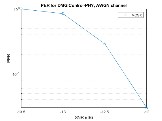
Plot Packet Error Rate vs SNR Results
figure;
semilogy(snrVec,packetErrorRate,'-o');
grid on;
xlabel('SNR (dB)');
ylabel('PER');
legend('MCS 0');
title('PER for DMG Control-PHY, AWGN channel');
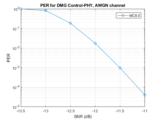
Further Exploration
The number of packets tested at each SNR point is controlled by two parameters: maxNumErrors and maxNumPackets. For meaningful results, it is recommended that these values should be larger than those presented in this example. Increasing the number of packets simulated allows the PER under different scenarios to be compared. As an example, the figure below was created by running the example for a PSDULength of 256 bytes, maxNumErrors:1000 and maxNumPackets: 100000.
Selected Bibliography
IEEE Std 802.11™-2020. IEEE Standard for Information Technology - Telecommunications and Information Exchange between Systems - Local and Metropolitan Area Networks - Specific Requirements - Part 11: Wireless LAN Medium Access Control (MAC) and Physical Layer (PHY) Specifications.
Local Functions
The following local function is used in this example:
dmgControlDespread: De-spread the receive signal
function [y,SF] = dmgControlDespread(rx)
    SF = 32; % Spreading factor
    dataField = rx.*exp(-1i*pi/2*(0:size(rx,1)-1).'); % De-rotate symbols
    Ga = wlanGolaySequence(SF); % Generate Golay sequence
    y = (reshape(dataField,SF,length(dataField)/SF)'*Ga)/SF;
end
SNR -13.5 completed after 11 packets, PER: 1
SNR -13 completed after 13 packets, PER: 0.84615
SNR -12.5 completed after 38 packets, PER: 0.28947
SNR -12 completed after 100 packets, PER: 0.03
SNR -11.5 completed after 100 packets, PER: 0
SNR -11 completed after 100 packets, PER: 0
SNR -10.5 completed after 100 packets, PER: 0