Results for
That's the question: Given four different positive numbers, a, b, c and d, provided in increasing order: a < b < c < d, find if any three of them comprise sides of a right-angled triangle. Return true if they do, otherwise return false .
I wrote this code but it doesn't pass test 7. I don't really understand why it isn't working. Can somebody help me?
function flag = isTherePythagoreanTriple(a, b, c, d)
a2=a^2
b2=b^2
c2=c^2
d2=d^2
format shortG
if a2+b2==c2
flag=true
else if a2+b2==d2
flag=true
else if a2+c2==d2
flag=true
else if c2+b2==d2
flag=true
else flag=false
end
end
end
end
end
That's the question:
The file cars.mat contains a table named cars with variables Model, MPG, Horsepower, Weight, and Acceleration for several classic cars.
Load the MAT-file. Given an integer N, calculate the output variable mpg.
Output mpg should contain the MPG of the top N lightest cars (by Weight) in a column vector.
I wrote this code and the resulting column vector has the right values but it doesn't pass the tests. What's wrong?
function mpg = sort_cars(N)
load cars.mat
sorted=sortrows(cars,4)
mpg = sorted(1:N,2)
end
Hi all,
I've translated a model from another piece of software (monolix) into simbio programmatically to make use of your very easy global sensitivity analysis system.
It looks a little something like this, for a 'single' line example:
r1 = addreaction(model,'InsI -> InsP');
r1.ReactionRate = 'InsI*kip/vi'; %- is + panc
k1 = addkineticlaw(r1, 'Unknown');
Multiplied about 20 fold, as you can see I have included my volumes within the reaction rates myself (vi). The model functions perfectly and I have corrected the outputs at the end:
[time, x, names] = sbiosimulate(model,csObj,dObj1);
x(:,1) = x(:,1)/vi;
So that they are in concentration, as needed. However, when it comes to sensitivity analysis because I have corrected them post-model it is technically incorrect, it is analysing the absolute quantities. This is quite noticible in the sensitivity to the volumes.
Is there an easy fix to this, I've had to fight dimensionality with units in the past using simbio and I'd be great if there was some way of dividing a compartment output by a volume, for example. It is a functionality that exists in monolix, so I was hopeful it might here!
Thank you for your time.
EDIT:
I think I've worked it out, I had to refactor my model to operate in concentrations, just refitting it now. Now I should just be able to use unitless compartments.
I am trying to make a simulink model to use a MPC to reduce power consumption of HVAC system in an electric vehicle during cool down from ambient temperature to a set point temperature. Any help regarding this would be appreciated
Kindly help me correct this code to function properly. I am just learning MATLAB. i cannot get the output in abc frame. This is the code:
%----------- Define input and state parameters-----------------------------
clc
v_dc = 350; % DC input voltage in V
m = 0.841; % modulation index
C = 4000e-6; % DC buss capacitance in uf
L_1 = 2.5e-3; % Inverter side inductance in mH
L_2 = 2.5e-3; % Load side inductance in mH
L = 0; % load inductance
C_f = 10e-6; % filter capacitance in uf
R_f = 0.7; % damping resistance in ohms
R_L = 20; % load resistance in ohms
f_s = 10e3; % switching frequency
f = 60; % System frequency
R_s = 0.01; % Capacitance of the DC circuit
I_d = 8.594; % steady state current
w = 2*pi*f; % System angular Frequency
% Define initial steady state values
v_c = 349.4; i_d = 8.594; i_q = -0.213; v_df = 285; v_qf = -120; i_Ld = 8.594; i_Lq = 0.85;
%------------------S V P W M Generator-------------------------------------
% Define reference vector Uref
U_mag = m*v_dc/2; % Magnitude of Uref
% Define switching vectors
U1 = [v_dc/2;0]; % Vector Q1
U2 = [v_dc/4;sqrt(3)*v_dc/4]; % Vector Q2
U3 = [-v_dc/4;sqrt(3)*v_dc/4]; % Vector Q3
U4 = [-v_dc/2;0]; % Vector Q4
U5 = [-v_dc/4;-sqrt(3)*v_dc/4]; % Vector Q5
U6 = [v_dc/4;-sqrt(3)*v_dc/4]; % Vector Q6
% Define sector angles
theta1 = pi/6;
theta2 = pi/2;
theta3 = 5*pi/6;
theta4 = 7*pi/6;
theta5 = 3*pi/2;
theta6 = 11*pi/6;
% Define duty cycles for each switch using a for loop
for t=0:1/f_s:1/f % Time variable from 0 to one cycle of system frequency with steps of switching frequency
U_phase = w*t; % Phase of Uref (t is time variable)
U_alpha = U_mag*cos(U_phase); % Alpha component of Uref
U_beta = U_mag*sin(U_phase); % Beta component of Uref
if (0 <= U_phase) && (U_phase < theta1) % Sector 1
T1 = (sqrt(3)*U_beta + U_alpha)/(2*v_dc);
T2 = (-sqrt(3)*U_beta + U_alpha)/(2*v_dc);
T0 = 1 - T1 - T2;
d_a(round(t)+1) = T1 + T0/2;
d_b(round(t)+1) = T2 + T0/2;
d_c(round(t)+1) = T0/2;
elseif (theta1 <= U_phase) && (U_phase < theta2) % Sector 2
T3 = (sqrt(3)*U_beta - U_alpha)/(2*v_dc);
T2 = (sqrt(3)*U_beta + U_alpha)/(2*v_dc);
T0 = 1 - T3 - T2;
d_a(round(t)+1) = T0/2;
d_b(round(t)+1) = T2 + T0/2;
d_c(round(t)+1) = T3 + T0/2;
elseif (theta2 <= U_phase) && (U_phase < theta3) % Sector 3
T3 = (sqrt(3)*U_beta - U_alpha)/(2*v_dc);
T4 = (-sqrt(3)*U_beta - U_alpha)/(2*v_dc);
T0 = 1 - T3 - T4;
d_a(round(t)+1) = T0/2;
d_b(round(t)+1) = T0/2;
d_c(round(t)+1) = T3 + T0/2;
elseif (theta3 <= U_phase) && (U_phase < theta4) % Sector 4
T5 = (-sqrt(3)*U_beta + U_alpha)/(2*v_dc);
T4 = (-sqrt(3)*U_beta - U_alpha)/(2*v_dc);
T0 = 1 - T5 - T4;
d_a(round(t)+1) = T5 + T0/2;
d_b(round(t)+1) = T0/2;
d_c(round(t)+1) = T4 + T0/2;
elseif (theta4 <= U_phase) && (U_phase < theta5) % Sector 5
T5 = (-sqrt(3)*U_beta + U_alpha)/(2*v_dc);
T6 = (sqrt(3)*U_beta + U_alpha)/(2*v_dc);
T0 = 1 - T5 - T6;
d_a(round(t)+1) = T5 + T0/2;
d_b(round(t)+1) = T6 + T0/2;
d_c(round(t)+1) = T0/2;
elseif (theta5 <= U_phase) && (U_phase < theta6) % Sector 6
T1 = (sqrt(3)*U_beta + U_alpha)/(2*v_dc);
T6 = (sqrt(3)*U_beta - U_alpha)/(2*v_dc);
T0 = 1 - T1 - T6;
d_a(round(t)+1) = T1 + T0/2;
d_b(round(t)+1) = T0/2;
d_c(round(t)+1) = T6 + T0/2;
end
end
%-------------------------Define system matrices---------------------------
% Create Three-phase SVPWM VSI Inverter
% System matrix Nx-by-Nx matrix
A = [-1/(C*R_s),-sqrt(3)*m/(2*C),0,0,0,0,0;
sqrt(3)*m/(3*L_1),-R_f/(3*L_1),w,-1/(2*L_1),-sqrt(3)/(6*L_1),-R_f/(3*L_1),0;
0,-w,-R_f/(3*L_1),-sqrt(3)/(6*L_1),-1/(2*L_1),0,R_f/(3*L_1);
0,1/(2*C_f),-sqrt(3)/(6*C_f),0,w,-1/(2*C_f),sqrt(3)/(6*C_f);
0,sqrt(3)/(6*C_f),1/(2*C_f),-w,0,-sqrt(3)/(6*C_f),-1/(2*C_f);
0,R_f/(3*(L_2+L)),0,1/(2*(L_2+L)),sqrt(3)/(6*(L_2+L)),((-3*R_L-R_f)/(3*(L_2+L))),w;
0, 0, R_f/(3*(L_2+L)), -sqrt(3)/(6*(L_2+L)), 1/(2*(L_2+L)), -w, ((-3*R_L-R_f)/(3*(L_2+L)))];
% Define input matrix
B = [1/(C*R_s),-sqrt(3)*i_d/(2*C);d_a*v_dc,(sqrt(3)*v_c)/L_1;d_b*v_dc,0;d_c*v_dc,0;0,0;0,0;0,0]; % Nx-by-Nu input matrix
% Define output matrix
C = [0 1 0 0 0 0 0; % Ny-by-Nx matrix
0 0 1 0 0 0 0;
0 0 0 1 0 0 0;
0 0 0 0 1 0 0;
0 0 0 0 0 1 0;
0 0 0 0 0 0 1];
% Feedthrough matrix
D = zeros(6, 2); % Ny-by-Nu matrix
% create state-space model object
sys = ss(A,B,C,D);
% Define initial conditions and input
x0 = [v_c; i_d; i_q; v_df; v_qf; i_Ld; i_Lq]; % Initial state vector
t = 0:1e-6:0.5; % Time vector for simulation
u = repmat([v_dc;m],1,length(t)); % repeat u for each time step
% Simulate the system
[y, ~, x] = lsim(sys, u, t, x0);
% Extract the states
v_c_sim = x(:, 1);
i_d_sim = x(:, 2);
i_q_sim = x(:, 3);
v_df_sim = x(:, 4);
v_qf_sim = x(:, 5);
i_Ld_sim = x(:, 6);
i_Lq_sim = x(:, 7);
% Extract the outputs
v_abc_sim = y(:, 1:3);
i_abc_sim = y(:, 4:6);
v_dq_sim = y(:, 4:5);
i_dq_sim = y(:, 2:3);
% Plot the variables
figure;
subplot(4, 2, 1);
plot(t, v_c_sim);
xlabel('Time');
ylabel('v_c');
title('Capacitor Voltage');
subplot(4, 2, 2);
plot(t, i_d_sim);
xlabel('Time');
ylabel('i_d');
title('d-Axis Current');
subplot(4, 2, 3);
plot(t, i_q_sim);
xlabel('Time');
ylabel('i_q');
title('q-Axis Current');
subplot(4, 2, 4);
plot(t, v_df_sim);
xlabel('Time');
ylabel('v_df');
title('d-Component Filter Voltage');
subplot(4, 2, 5);
plot(t, v_qf_sim);
xlabel('Time');
ylabel('v_qf');
title('q-Component Filter Voltage');
subplot(4, 2, 6);
plot(t, i_Ld_sim);
xlabel('Time');
ylabel('i_Ld');
title('d-Axis Load Current');
subplot(4, 2, 7);
plot(t, i_Lq_sim);
xlabel('Time');
ylabel('i_Lq');
title('q-Axis Load Current');
% Perform coordinate transformation from dq frame to abc frame for currents
i_a_sim = cos(w*t)*i_d_sim - sin(w*t)*i_q_sim;
i_b_sim = cos(w*t - 2*pi/3)*i_d_sim - sin(w*t - 2*pi/3)*i_q_sim;
i_c_sim = cos(w*t + 2*pi/3)*i_d_sim - sin(w*t + 2*pi/3)*i_q_sim;
% Perform coordinate transformation from dq frame to abc frame for voltages
v_a_sim = cos(w*t)*v_df_sim - sin(w*t)*v_qf_sim;
v_b_sim = cos(w*t - 2*pi/3)*v_df_sim - sin(w*t - 2*pi/3)*v_qf_sim;
v_c_sim = cos(w*t + 2*pi/3)*v_df_sim - sin(w*t + 2*pi/3)*v_qf_sim;
Many thanks
I am trying to simulate model of blood lymphocyte count from a paper using Simbiology. The rate of in or out following circadian rythym is kp(t)=km + kb cos [(t-tpeak)*2pi/24] Where and how do I write the expression ? I dont think I can write in repeated assignment ?
I recently have found that I am no longer able to give my difficulty rating for questions on Cody after sucessfully completing a question. This is obviously not a big deal, I was just wondering if this was an issue on my end or if there was some change that I was not aware of.
The option to rate does not pop up after solving a problem, and the rating in general does not even show up anymore when answering questions (though it is visible from problem groups).
I am currently facing a compatibility issue when attempting to load a SimBiology model created in MATLAB 2021a into MATLAB 2023a. Specifically, the code capture functionality does not seem to be working.
If anyone has encountered a similar situation or has insights on how to capture the code for a SimBiology model created in an older version of MATLAB, I would greatly appreciate your guidance. Are there any alternative methods or specific steps that can be followed to ensure successful code capture?
Thank you in advance for your time and expertise.
The MATLAB Answers community is an invaluable resource for all MATLAB users, providing selfless assistance and support. However, with the emergence of AI-based chatbots, like chatGPT, there may be concerns about the future relevance and utility of the MATLAB Answer community. What are your thoughts?
Hello, Recently I have started working on a thermal management project at my Institute. I am taking some hints from en example of EV thermal management provided by MATLAB. I am having an issue in deciding how the battery current and powertrain heat load is calculated as a function of vehicle speed. It would be helpful if someone could provide some links or references regarding this. (Also, attaching a screenshot of the example for better understanding)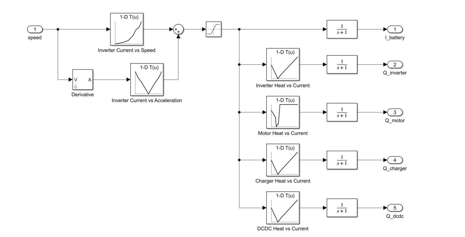
I am processing ocean and climate data (1982-2022). Here, I have table which having heatwaves events details. Now, I want to sort the data month wise and also seasonal wise (summer:October- February, and winter:March-September), and then i wanted to plot mean seasonal and trend.
Sample file is attached. length of original file may vary in size.
Thanks in addvance.
Hello,
can someone help me with HEV model? I have no experience with simulink modeling, maybe someone have any simple HEV models or any tutorials how to start everything? :)
Thank you.
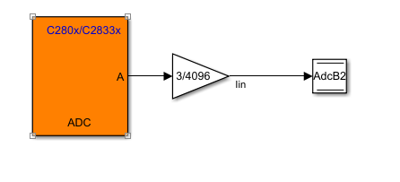
I am using simulink to generate a simple ADC sampling code. I configured ADC module in software mode, which updates the sampled value according to the sample time configured in the module. I set the sample time to 1e-4, 1e-5, 1e-6 respectively. But it seems that the sampling speed did not reach the value I set. I suspect it has something to do with the read and write operations, but I am not sure if that's the reason.
I also tried to do it using PWM event to trigger the start of conversion of ADC. Same problem happened. Because I connect a potentiometer and turn its knob slowly, the Graph on CCS is correct while when I turn it very quickly, the graph is not able to keep up with my movements. So the sampling rate is surely not enough. I wonder what I should do to successfully configure this model, thanks in advance!
Hello,
I have an Open Loop Transfer Function:
Gc(s)Gp(s) = aKp(1+Tis) / Tis(s+1+p)
It was decided for this system a=5, Ti=0.1 and p=0.5
What would the poles and zeroes be for this?
Ive done the other examples but this one looks very different to the other questions and it has me stuck.
Any help is appreciated and sorry if this is the wrong place to post such questions.
"The model is configured to create a SIL block, which is not supported for the selected hardware board. To resolve this, search for 'Create block' in the Configuration Parameters dialog box and set it to 'None' or 'PIL'.
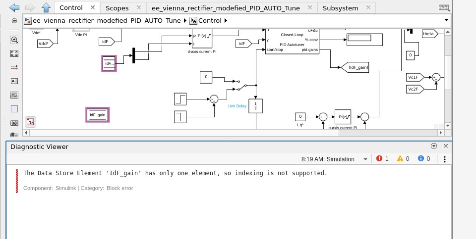
I am facing an issue in data store memory block using store memory Read and write Block in matlab simulink. I have attached the screen short in which the posed error has been depicted.
Hello,
i want to implement a Energy Storage System with a Battery and a Supercapacitor, where the Supercapacitor comes in when the Battery has a short circuit for an emergency system. How can i implement something like this ? I think the right way is to implement a function where a switch is controlled by the SOC of the two storage systems or ?
Hi, I am currently studying the effects of varying switching frequency towards the inverter and motor system efficiency. I am using the three-phase converter which the gate signal is sent by a PWM generator. Inside the PWM generator block, there is switching frequency parameter. Therefore, is it possible if I can tune the value of switching frequency by making it as input and receving the signal in Matlab Simulink similar with Vabc and Vdc instead of tuning from Matlab code?
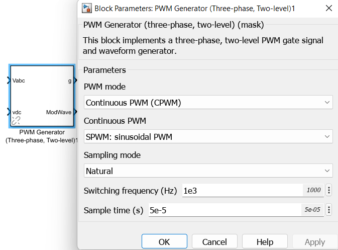
Hope to receive any comment or suggestion. Thank you.
Need some guidance on how to model the mutual inductance model from Simscape. The secondary side does not receive the voltage.
I want to understand this from the scratch, i will appreciate help and guidance very much.