Results for
Hello, I want to know if it is possible to create a signal from vectors in simulink, and in what way. Thank you very much in advance
My linear algebra book makes me solve a matrix with the help of a computer. When I tried to solve linear equations with an infinite number of solutions, Mathlab just makes some or all the entries zero. For example, with the set [1 2;2 4]=[0;0] it just gives back [0 0] for an answer. Is there a way for it to give back a parametrization of some kind?
THere are different PI controllers in FOC of Induction motor. flux PI, speed PI, i_d PI and I_q PI. How to tune all these pi controllers?
<https://www.google.com/url?sa=i&source=images&cd=&ved=2ahUKEwjs8d-b18fjAhVViHAKHQP-Bs8QjRx6BAgBEAU&url=https%3A%2F%2Fwww.researchgate.net%2Ffigure%2Fflow-diagram-for-indirect-field-oriented-control-of-an-induction-motor_fig2_271706832&psig=AOvVaw2Z-y_r0-L7Xi6buKrGjkno&ust=1563855853965078> Here is one of the example. How to do this?
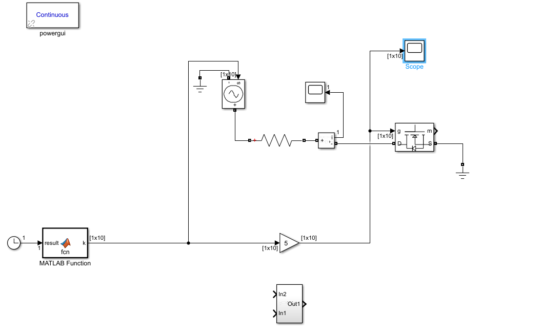
I'm working on a simulink design, using MATLAB function. By the benefit of the MATLAB function, I got 1x10 array of which values are like [1 0 0 1 0 0 1 0 0 0], I want these values to be sent to the MOSFET's gate sequentially. I thought it would have been done with 'For loop' to send it sequentially but I found out that's not possible since it's just sensed the latest column's value so that I just saw 0 in my scope. Any idea how to do it properly? Below you can see the simulink design.
Hello: your help is greatly appreciated, I am trying to solve the following pde numerically with ode45 (if possible). There are three equations in total. I keep getting an error. know parameters: v, D(j), KL(j), cs(j) The IC and BC are provided in the m.file. pde:
    % code
% Initial, final values of independent variable
tspan = [0 7];
P=1, F2=2, F3=3;
c_initial_1= zeros(N+1,1);
c_initial_2= zeros(N+1,1);
c_initial_3= zeros(N+1,1)
if t == 0
c_initial_2(1,2) = cs(2)
c_initial_3(1,3) = cs(3)
c_initial_1(1,1) = cinj
end
  [t, c, kF2, kF3, kP, n2, m2, n3, m3, q, r] = ode45(@ode, tspan, c_initial_1,c_initial_2, c_initial_3);
function [dcdt] = ode(t, c, k2, k3, kP, n2, m2, n3, m3, q, r)
global N dx dxs
dcdt = zeros(N,N)
for i = 1:N
    for j = P:F3 % j== 1:3 1=persulfate, 2 Fraction 2, and 3 Fraction 3
        if j == 1
            epsilon = 1
        else
            epsilon = 0
        end
        dcdt(i, j) = (-v/(2*dx))*(c(i+1,j)-c(i-1,j))+(D(j)/dxs)*(c(i+1,j)...
            -2*c(i,j)-c(i-1,j))+(1-epsilon)*kL(j)*(cs(j)-c(i,j))- ...
            (1-epsilon)*k(j)*(c(i,j)^n(j)*(c(i,1)^m(j))- ...
            epsilon*kP*(c(i,j+epsilon)+c(i,j+2*epsilon))^q *c(i,1)^r
        dcdt(N+2,j) = dcdt(N-1,j)
        dcdt(0,j) = dcdt(2,j)
        if t == 0
            dcdt(1,P) = cinj
        end
    end
end
end
end
dc(i,j)/dt=-v*(dc(i,j)/dx)+D(j)*d/dx(dc(i,j)/dx)+(1-epsilon)*kL(j)*(cs(j)-c(i,j))+(1-epsilon)*k(j)*c(i,j)^n(j) * c(i,1)^m(j) + epsilon*kp*[c(i,j+epsilon)+c(i,j+2*epsilon)]^r * c(i,1)^q
Good day everyone,
I'm trying to simulate a single phase transformator by using Simulink. I've got the current values: R1 = 3 Ohm R2 = 0.03 Ohm X1 = 6.5 Ohm X2 = 0.07 Ohm Rc = 100k Ohm Xm = 15k Ohm f = 60 Hz Uprim = 2400V Usec = 240V S = 29kVA cos Phi = 0.8
And I've made the current calculations: L1 = X1/2*pi*f = 17,24 mH L2 = X2/2*pi*f = 185.68 uH Lm = Xm/2*pi*f = 39.79 H S = Urms*Irms => Irms = 120.83 A P = Urms*Irms*cos Phi = 23200 W Q = Urms*Irms*sin Phi = 17400 VAr Q>0 so Q = ohms-inductive => QL = 17400, QC = 0
I've made the current circuit and simulated it, but somehow my secondairy output voltage is only at 225Vrms. Can someone explain to me why that's the case? Did do something wrong in my calculations or in my simulation?
i am confused about how to run as a closed loop. how to do closed-loop control of phase shift using matlab. i am using c2000 embedded by Matlab.
Hi, I am intrigued by the idea of using the simbiology stochastic solvers for a project that I have so far coded in the idnlgrey framawork.
Some of the ODE right hand sides (ionic fluxes) in my model are given via fitobjects.
My question is: can I use a fit object in simbiology? Or should I figure out an analytical form and use it as a custom reaction rate?
Thanks, Francesco
On using Simbiology, I am realizing how wonderful it is! It is equivalent and infact better than much commercial software available in the market for hefty prices (not to name anyone in purpose). Moreover, the product is backed up by the world leaders in software engineering - MATLAB (which gives more confidence to the product). It would be very helpful if someone can share the list or some of the PubMed indexed publication on population pharmacokinetics in which Simbiology is utilized for modeling and computation.
Identification of model (one compartment, two compartments or three compartments) which a drug follows is an important step before population pharmacokinetic modeling. I am aware that the graph between the concentration vs time, gives an idea of the number of compartment a drug follows.
But is there a standard way to explore and determine the number of compartment a drug follows in a more objective manner. This would also be helpful to determine the model in which the data needs to be fit. In addition, a note on determining the order of reaction is also welcomed and would make the discussion complete.
Fulden and I will have a booth at PAGE next week. Come and chat with us to learn the latest with MATLAB and SimBiology for PK/PD, PBPK, and QSP modeling.
I use Simbiology for population PK-PD model development. During the model fitting of data, I understand that the model diagnostics play a major decisive role in selecting the suitable model. Hence would like to make it clear regarding the interpretation of the model diagnostics.
If for example, I have two models. First model: DFE= 411, LogLikelihood = - 807.6 (minus 807.6), AIC = 1633.2 , BIC = 1647.2 and RMSE = 1.92 Second model: DFE= 410, LogLikelihood = - 888.8 (minus 888.8), AIC = 1797.6 , BIC = 1813.2 and RMSE = 0.34 Which among the model is better and why? What are the individual interpretation of DFE, LogLikelihood, AIC, BIC and RMSE?
In PK-PD research paper generally, they take Objective Function value as decisive model diagnostics. What is the Objective Function Value in Simbiology? I did some literature search and found that Objective Function Value is -2 times LogLikelihood value? So should I multiply the LogLikelihood value given in Simbiology by - 2 to obtain Objective Function Value? Moreover, if the LogLikelihood value is multiplied with -2 then the entire interpretation will be changing (as minus will reverse the direction). So please guide in this regard and give your valuable inputs.
Bonjour A tous,
Je vous écris pour solliciter votre aide si possible. Je travaille en ce moment sur un projet qui consiste a un traitement d'image.
J'utilise une camera thermique associée a une logiciel. Avec ce logiciel, j'enregistre une film de 4 secondes. En gros j'ai une vidéo constituée de 100 images.
Une image comprend 90 pixels donc les valeurs de ces pixels sont reparties en sous forme matricielle (10x9). Ce qui fait que pour les 100 images, j'ai 100 matrices.
L’idée c'est d'avoir une image moyenne donc une moyenne des 100 matrices.
Le problème c'est que je fais le traitement avec ce logiciel. Pour la suite des travaux j'utilise matlab.
J'ai donc besoin de créer un programme sous matlab qui me permet de lire le fichier recueilli par ce logiciel de traitement d'image en me refaisant sortir de façon automatique une moyenne de ces 100 matrices.
Je vous joins en copie un exemple de ce fichier.
J'ai donc besoin de piste pour le programmer.
Je vous remercie d'avance.
Bien cordialement,
Hi I would like to improve my skills in PK/PD modelling using Simbiology. Are you going to organize any courses in the near future? Many thanks Anas
Hi, In my circuit, I have an element for which I don't have its equivalent circuit. What I have is a lookup table of its frequency response (magnitude and phase), which is complicated and cannot be represented by a lumped parameters equivalent circuit, and also some of its elements are frequency-dependent. Even if I do obtain somehow its transfer function Laplace representation (using e.g. "System identification" toolbox, and I want to add it to my circuit simulation (Simscape Electrical) as a block.
Does anyone have an idea how to do it? Thank you!
We've been hearing from more and more customers who are interested in using Xilinx's new Zynq UltraScale+ devices in power electronics control applications. The attraction appears to be the dual-core ARM Cortex-R5 processors, which are well suited to hard real time applications. Are you looking at Zynq UltraScale+ MPSoCs as a platform for power electronics control? If so, we'd love to hear from you as we look at support for these devices.
In the meantime, MathWorks offers a reference design example for FOC motor control on Zynq-7000 devices that many customers have used as a basis for developing Simulink models for C and HDL code generation.
Hi guys could u guys please help me explain what is happening on this 3 graphs. I am an electrical student and just to be honest i am not a smart student but I'm willing to learn. Please do help me.Ive got my simulation i managed to generate perfect sin wave but i just couldn't explain on the graphs i simulated.
With the need for higher sampling frequencies, power electronics control engineers are moving some of their controller implementations to FPGAs or FPGA-based SoCs. Besides the use of wide-band gap semiconductors (GaN and SiC), what other reasons are driving the need for higher controller sampling frequencies? Let us know your thoughts.
If you have not seen this yet, in Release 2018b we added several examples to Simulink Control Design that show how to use this product to tune the gains of field-oriented controllers.
The first two examples make use of Closed-Loop PID Autotuner block . We show how to use this block to tune multiple loops in the motor control system, one loop at a time.
One of the examples shows tuning the controller gains for a PMSM:
Tune Field-Oriented Controllers Using Closed-Loop PID Autotuner Block
The other example shows how to tune four loops for an asynchronous machine (inductance motor):
Tune Field-Oriented Controllers for an Asynchronous Machine Using Closed-Loop PID Autotuner Block
This approach works well when you have initial gains that provide stable response, and you want to fine tune the controller to improve performance.
What do you do when you start with a new design and need to design your controller from scratch? That is what the third example is showing. Here we design all 3 loops (id, iq, speed) for a PMSM by running an AC sweep to compute a frequency response, then identifying a state-space model using System Identification Toolbox, and finally tuning all 3 loops simultaneously to provide desired performance.
Check it out here:
Tune Field-Oriented Controllers Using SYSTUNE
What do you think about these examples?
Share your opinion.
Arkadiy
On Wednesday, April 17, 12-1 PM EDT, Dr. Ing. Markus Rehberg, QSP Scientist at Sanofi in Frankfurt (Germany) will show how Sanofi and Rosa & Co created a QSP model for Rheumatoid Arthritis, using SimBiology, that transformed the way Sanofi uses and implements data in drug research and early development.
I invite you to register for the webinar, and afterward let me know what you think: https://register.gotowebinar.com/register/325575685872200717