Symmetrical Components | What Is 3-Phase Power?, Part 4
From the series: What Is 3-Phase Power?
In 3-phase electrical power systems, system operation can either be balanced or unbalanced. Unbalanced operation is undesirable, and there needs to be a good way to analyze system imbalance so you can assess the severity of an imbalance, define appropriate settings for protection relays, and drive appropriate control mechanisms to address an imbalance. Learn how to effectively analyze system imbalance through symmetrical components.
You will learn:
- How a 3-phase voltage/current is decomposed into positive-sequence, negative-sequence, and zero-sequence symmetrical components
- The circumstances under which negative-sequence and zero-sequence components will show up in a system response
- How system faults can be described by symmetrical components
- How to compensate for a system imbalance using negative-sequence current injection
Published: 19 May 2022
Hello, everyone. My name is Graham Dudgeon and welcome to part 4 in our series of tutorials on 3-phase power. The aim of the video series will be to build up our engineering knowledge on the design, analysis, and operation of 3-phase electrical power systems. Today, we will explore symmetrical components which are invaluable for analyzing unbalanced system operation, including unbalanced fault conditions.
Here, we can see a visual representation of a balanced system, on the left, and an unbalanced system, on the right. Balanced 3-phase voltage has equal voltage magnitudes in each phase with phase B lagging phase A by 120 degrees and phase C leading phase A by 120 degrees.
Similarly, balanced 3-phase current has equal current magnitudes in each phase with phase B lagging phase A by 120 degrees and phase C leading phase A by 120 degrees. An unbalanced system is anything that does not meet this criteria. You can see the unbalanced vectors in this example deviate from both nominal magnitude and nominal phase.
Unbalanced operation is undesirable and we need a good way to analyze system and balance so we can assess the severity of an imbalance, define appropriate settings for protection relays, and also to drive appropriate control mechanisms to address an imbalance. The way that we can effectively analyze system imbalance is through the use of symmetrical components.
Symmetrical components are used to express an unbalanced three-phase voltage or current as a combination of three balanced voltages or currents. Those three balanced components are referred to as positive sequence, negative sequence, and zero sequence.
We won't cover the math of symmetrical components in this tutorial. Plenty of textbooks are available that cover the math in detail. We'll instead show you what they are, using animation in MATLAB.
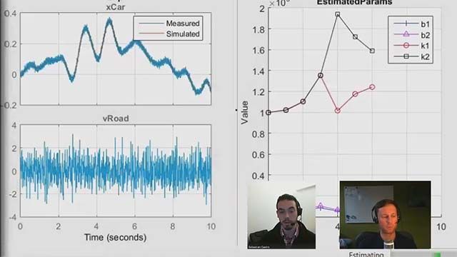
The animations I will show you are driven from simulated data. Here is a Simscape Electrical model I am using for this tutorial. With this model, I can explore various unbalanced characteristics.
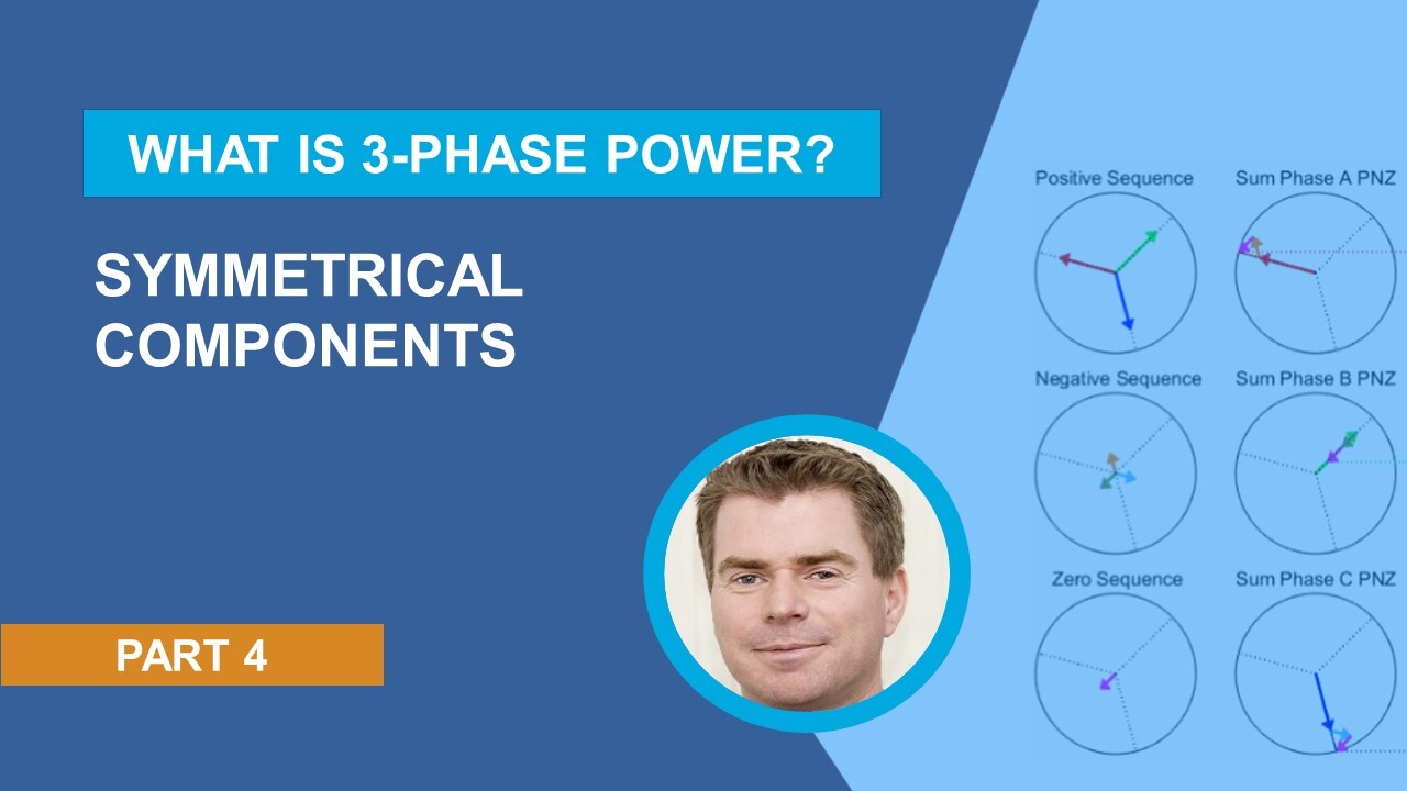
Here is a visualization of symmetrical components for balanced current. Let me orient you around what we are seeing and we'll go column by column. First, some nomenclature.
Positive sequence components are appended with a one-- A1, B1, C1. Negative sequence with a two-- A2, B2, C2. And zero sequence with a zero-- A0, B0, C0.
The column on the left shows the sequence components. At the top is the positive sequence, the middle is a negative sequence, and the bottom is the zero sequence. Note that for a balanced system only positive sequence exists and the positive sequence is equal to the original vectors.
The middle column is where we add the sequence vectors to reconstruct the original vectors. At the top is phase A reconstruction, the middle is phase B reconstruction, and the bottom is phase C reconstruction. Note that because negative sequence and zero sequence are zero then all we see in this column are the positive sequence vectors.
In the third column, we separate our original vectors to compare with the reconstructed vectors. With phase A at the top, phase B in the middle, and phase C at the bottom. I also show the combined original vectors on the right.
Note that the reconstructed vectors match the original vectors. Now, let's take a look at an unbalanced system that has no neutral path. To imbalance the system, I'll increase the resistance in phase B of the system load.
You can see in our left column that we now have a negative sequence. Also note the positive sequence is reduced in magnitude. As this example has no ground or neutral path, we have no zero sequence current. Note that the phase ordering of the vectors in positive sequence is A, B, C. B lags phase A and C lags phase B.
In the negative sequence, the phase ordering of the vectors is A, C, B. C lags phase A and B lags phase C. In the middle column, we add the sequence vectors to reconstruct the original vectors.
For phase A reconstruction, we add A1, A2, and A0. For phase B reconstruction, we add B1, B2, and B0. And for phase C reconstruction, we add C1, C2, and C0.
Note that we have a measure of how unbalanced the system is with the negative sequence being approximately 41.5% of nominal for this example. Now, we'll look at what happens when we have a neutral path in an imbalanced system.
You can see in our left column that we now have a zero sequence component. Note that the three zero sequence components for each phase are overlaid. What this actually shows us is that a single phase current flows through the neutral path with the phase being equal to the zero sequence phase and a magnitude equal to three times the zero sequence magnitude.
In the middle column, we add the sequence vectors to reconstruct the original vectors and we can see that the reconstructed vectors match the original vectors.
Next, we'll look at the symmetrical components for line current during single line-to-neutral faults. In the column on the left, we have a line A-to-neutral fault, the middle column shows a line B-to-neutral fault, and the right column shows a line C-to-neutral fault. Note that I made the fault resistance equal in each case for direct comparison. I have three observations.
First, the positive sequence is equal in each case. Second, the negative sequence magnitudes are equal but the phase shift is different. A2 is in phase with A1 for the line A-to-neutral fault. C2 is in phase with A1 for the line B-to-neutral fault. And B2 is in phase with A1 for the line C-to-neutral fault.
Third, the zero sequence magnitudes are equal but the zero sequence is in phase with its corresponding fault. Symmetrical components are invaluable for identifying what fault has occurred and symmetrical components are commonly used in protection relay algorithms.
Another use for symmetrical components is in imbalance compensation. In this example, I have introduced a load on line A which will cause an imbalance to the supply voltage for a three-phase load which manifests itself as a negative sequence component in this case.
What we do is we inject the anti-phase of the negative sequence current back into the system. In practice, we use power converters to perform this task but I'll use an ideal source to demonstrate the concept.
At the top, we see the load current, in the middle is the compensation current, that is the current we inject into the system, and in the bottom is the line current. I have also shown the before and after negative sequence components. Note that the compensation negative sequence is in anti-phase with the line negative sequence after compensation is activated.
We've succeeded in balancing the load current but at the expense of introducing a larger imbalance into the line current. What you're seeing here is a rather extreme case so we can clearly see what's happening. Imbalances in practice are typically less severe than this.
One final observation-- note that the compensation current is only negative sequence. If you look carefully at the instantaneous waveforms, you will see that the phase order is A, C, B rather than A, B, C.
So in summary, a balanced three-phase supply has equal magnitudes in each phase with phase B lagging phase A by 120 degrees and phase C leading phase A by 120 degrees.
An unbalanced system is anything that does not meet the above criteria. Unbalanced systems can be represented by symmetrical components which consist of three sequences-- positive sequence, negative sequence, and zero sequence.
In a balanced system, the positive sequence is equal to system response. A negative sequence and zero sequence are zero. Zero sequence is a measure of the ground or neutral current flow in an unbalanced system which has a ground or neutral path.
Symmetrical components are used to characterize faults. And imbalances in system loading may be compensated for by injecting the anti-phase of the negative sequence current back into the system. I hope you found this information useful. Thank you for listening.


Select a Web Site
Choose a web site to get translated content where available and see local events and offers. Based on your location, we recommend that you select: United States.
You can also select a web site from the following list
Americas
- América Latina (Español)
- Canada (English)
- United States (English)
Europe
- Belgium (English)
- Denmark (English)
- Deutschland (Deutsch)
- España (Español)
- Finland (English)
- France (Français)
- Ireland (English)
- Italia (Italiano)
- Luxembourg (English)
- Netherlands (English)
- Norway (English)
- Österreich (Deutsch)
- Portugal (English)
- Sweden (English)
- Switzerland
- United Kingdom (English)