BPSK Modulator Baseband
Modulate using BPSK method
Libraries:
Communications Toolbox /
Modulation /
Digital Baseband Modulation /
PSK
Communications Toolbox HDL Support /
Modulation /
PM
Description
The BPSK Modulator Baseband block modulates a signal by using the binary phase shift keying (BPSK)
method. The output is a baseband representation of the modulated signal. The input
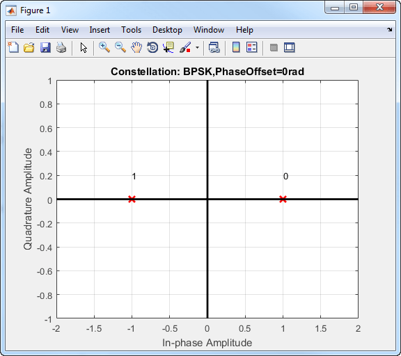
signal must be a discrete-time binary-valued signal. If the input bit is 0 or 1, then
the modulated symbol is exp(jϕ) or -exp(jϕ), respectively. The Phase offset
(rad) parameter specifies the value of ϕ in radians.
Examples
Use a CRC code to detect frame errors in a noisy BPSK signal.
In the cm_ex_crc_noisy_bpsk_frames model, the CRC generator and detector pair use a standard CRC-4 polynomial,  . The length of the CRC is 4 bits as determined by the degree of the polynomial. The number of checksums per frame is 1, so the full transmission frame has one CRC appended at the end.
A binary signal frame gets a CRC code appended to the end of the frame. BPSK modulation is applied to the signal and the signal passes through an AWGN channel. The signal is demodulated, and then a CRC syndrome detector removes the CRC and calculates the CRC errors.
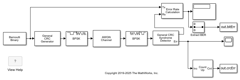
Generate 12-bit frames of binary data and append CRC bits. Based on the degree of the polynomial, 4 bits are appended to each frame. Apply BPSK modulation and pass the signal through an AWGN channel. Demodulate and use the CRC detector to determine if the frame is in error.
The results of the CRC detection are compared to a BER calculation.
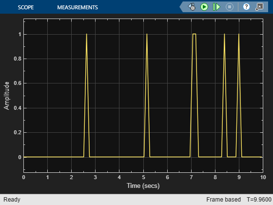
Number of bit errors detected:  6
Number of crc errors detected:  5
Extended Examples
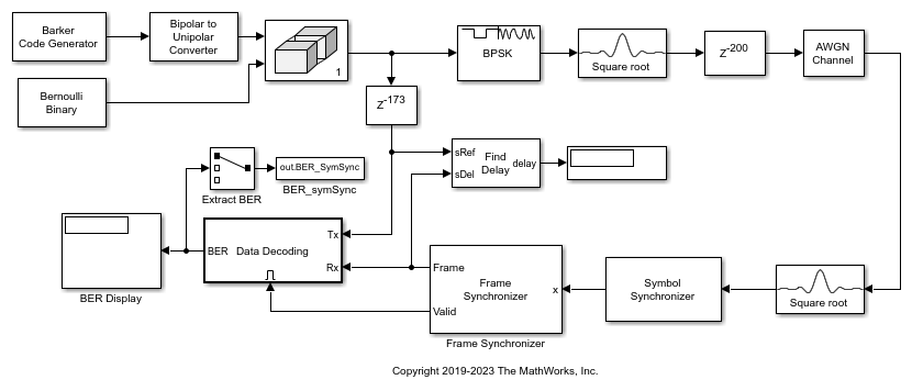
Frame Synchronization Using Barker Code Preamble
Use a length 13 Barker code frame preamble for frame synchronization of data bits.
Ports
Input
Output
Parameters
Block Characteristics
More About
The Data Type Assistant helps you set data
attributes. To use the Data Type Assistant, click ![]() . For more information, see Specify Data Types Using Data Type Assistant (Simulink).
. For more information, see Specify Data Types Using Data Type Assistant (Simulink).
Algorithms
Phase modulation is a linear baseband modulation technique in which the message modulates the phase of a constant amplitude signal. Binary Phase Shift Keying (BPSK) is a two phase modulation scheme, where the 0’s and 1’s in a binary message are represented by two different phase states in the carrier signal
for where:
ϕn = πm + ϕ, m∈{0,1}.
ϕ is the initial phase offset.
Eb is the energy per bit.
Tb is the bit duration.
fc is the carrier frequency.
In MATLAB®, the baseband representation of a BPSK signal is
The BPSK signal has two phases: 0 and π.
The probability of a bit error in an AWGN channel is
where N0 is the noise power spectral density.
Extended Capabilities
Version History
Introduced before R2006a
See Also
Blocks
- BPSK Demodulator Baseband | M-PSK Modulator Baseband | QPSK Modulator Baseband | DBPSK Modulator Baseband