OFDM Modulator Baseband
Modulate using OFDM method
Libraries:
Communications Toolbox /
Modulation /
Digital Baseband Modulation /
OFDM
Description
The OFDM Modulator Baseband block modulates a frequency domain signal by using the orthogonal frequency division multiplexing (OFDM) method. For more information, see Orthogonal Frequency Division Multiplexing. The output is a baseband representation of the OFDM-modulated signal.
This icon shows the block with all ports enabled.
![]()
Examples
The model filters an oversampled OFDM modulated signal through a single-input single-output (SISO) channel. After channel filtering, it demodulates the signal and compares the original data to the demodulated output.

The cm_oversample_ofdm_siso model:
Generates random integer data and pilot input symbols.
16-QAM modulates the data and pilot symbols.
OFDM-modulates the QAM-modulated signal. The OFDM modulator and demodulator pair process three symbols, with different pilot subcarrier indices and cyclic prefix lengths for each symbol. The OFDM signal contains data and pilots that the model generates at four times the sample rate.
Filters the OFDM-modulated signal through a SISO AWGN channel.
OFDM-demodulates and separately outputs the data and pilot signals.
16-QAM demodulates to the data and pilot symbols.
Computes symbol error rates for the data and pilot signals by using Error Rate Calculation blocks.
The model initializes variables used to configure block parameters by using the PreLoadFcn callback function. For more information, see Model Callbacks (Simulink).
Display the data and pilot symbol error rates.
The data had a 0.014636 symbol error rate for 126126 samples.
The pilots had a 0.016817 symbol error rate for 12012 samples.
The RMS block measures the OFDM-modulated signal scaled by a value proportional to the number of active subcarriers relative to the FFT size to confirm the signal power is approximately unity.
The measured RMS value is 0.98499.
Extended Examples

Digital Video Broadcasting - Terrestrial
Simulate part of the European Telecommunications Standards Institute (ETSI) EN 300 744 standard for terrestrial transmission of digital television signals.
Ports
Input
Output
Parameters
Block Characteristics
Data Types |
|
Multidimensional Signals |
|
Variable-Size Signals |
|
Algorithms
OFDM belongs to the class of multicarrier modulation schemes. Because the operation can transmit multiple carriers simultaneously, noise does not influence OFDM to the same degree as single-carrier modulation.
OFDM operation divides a high-rate data stream into low-rate data substreams by decomposing the transmission frequency band into a number of contiguous individually modulated subcarriers. This set of parallel and orthogonal subcarriers carry the data stream occupying almost the same bandwidth as a wideband channel. By using narrow orthogonal subcarriers, the OFDM signal gains robustness over a frequency-selective fading channel and eliminates adjacent subcarrier interference. Intersymbol interference (ISI) is reduced because the lower data rate substreams have symbol durations larger than the channel delay spread.
This image shows a frequency domain representation of orthogonal subcarriers in an OFDM waveform.

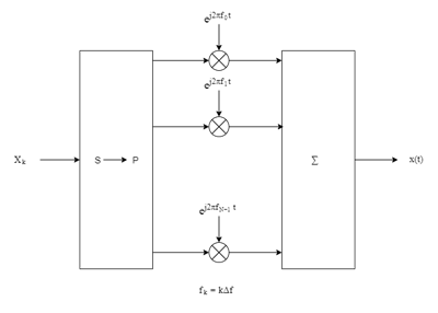
The transmitter applies inverse fast Fourier transform (IFFT) to N symbols at a time. Typically, the output of the IFFT is the sum of the N orthogonal sinusoids:
where {Xk} are data symbols, and T is the OFDM symbol time. The data symbols Xk are typically complex and can be from any digital modulation alphabet (for example, QPSK, 16-QAM, 64-QAM, etc.).
Note
The MATLAB implementation of the discrete Fourier transform normalizes the output of
the IFFT by 1/N. For more information, see Discrete Fourier Transform of Vector
on the ifft reference page.
The subcarrier spacing is Δf = 1/T, ensuring that the subcarriers are orthogonal over each symbol period:
An OFDM modulator consists of a serial-to-parallel conversion followed by a bank of N complex modulators, individually corresponding to each OFDM subcarrier.
Individual OFDM subcarriers are allocated as data, pilot, or null subcarriers.
As shown here, subcarriers are designated as data, DC, pilot, or guard-band subcarriers.

Data subcarriers transmit user data.
Pilot subcarriers are for channel estimation.
Null subcarriers transmit no data. Subcarriers with no data provide a DC null and serve as buffers between OFDM resource blocks.
The null DC subcarrier is the center of the frequency band with an index value of (
nfft/2 + 1) ifnfftis even, or ((nfft+ 1) / 2) ifnfftis odd.The guard bands provide buffers between adjacent signals in neighboring bands to reduce interference caused by spectral leakage.
Null subcarriers enable you to model guard bands and DC subcarrier locations for specific standards, such as the various 802.11 formats, LTE, WiMAX, or for custom allocations. You can allocate the location of nulls by assigning a vector of null subcarrier indices.
Similar to guard bands, guard intervals protect the integrity of transmitted signals in OFDM by reducing intersymbol interference.
Assignment of guard intervals is analogous to the assignment of guard bands. You can model guard intervals to provide temporal separation between OFDM symbols. The guard intervals help preserve intersymbol orthogonality after the signal passes through time-dispersive channels. You create guard intervals by using cyclic prefixes. Cyclic prefix insertion copies the last part of an OFDM symbol as the first part of the OFDM symbol.

OFDM benefits from the use of cyclic prefix insertion as long as the span of the time dispersion does not exceed the duration of the cyclic prefix.
Inserting a cyclic prefix results in a fractional reduction of user data throughput because the cyclic prefix occupies bandwidth that could be used for data transmission.
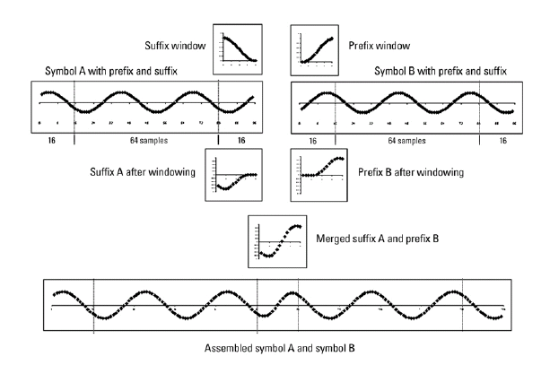
OFDM raised cosine windowing applies techniques described in [3] to limit spectral regrowth by creating a smooth transition between the last sample of one symbol and the first sample of the next symbol.
While the cyclic prefix creates a guard period in time domain to preserve orthogonality, an OFDM symbol rarely begins with the same amplitude and phase that it exhibits at the end of the prior OFDM symbol, which causes spectral regrowth and, therefore, spreads the signal bandwidth due to intermodulation distortion. To limit this spectral regrowth, you can create a smooth transition between the last sample of a symbol and the first sample of the next symbol by using a cyclic suffix and raised cosine windowing.
The discussion and figures in this section assume an oversampling factor of 1. To create the cyclic suffix, the operation appends the first NWIN samples of a given symbol to the end of that symbol. However, to comply with the IEEE® 802.11g standard, for example, the operation cannot arbitrarily lengthen the symbol. Instead, the cyclic suffix must overlap in time and is effectively summed with the cyclic prefix of the following symbol. The operation applies two, mathematically inverse, windows in this overlapped segment. The first raised cosine window applies to the cyclic suffix of symbol k and decreases from 1 to 0 over its duration. The second raised cosine window applies to the cyclic prefix of symbol k+1 and increases from 0 to 1 over its duration. This process provides a smooth transition from one symbol to the next.
The raised cosine window, w(t), in the time domain can be expressed as:
where:
T is the OFDM symbol duration including the guard interval.
TW is the duration of the window.
Adjust the length of the cyclic suffix by setting the window length, with suffix lengths set between 1 and the minimum cyclic prefix length. While windowing improves spectral regrowth, it does so at the expense of multipath fading immunity because of reduced redundancy in the guard band due to guard band sample values changes to implement intersymbol transition smoothing.
References
[1] Dahlman, E., S. Parkvall, and J. Skold. 4G LTE/LTE-Advanced for Mobile Broadband. London: Elsevier Ltd., 2011.
[2] Andrews, J. G., A. Ghosh, and R. Muhamed. Fundamentals of WiMAX. Upper Saddle River, NJ: Prentice Hall, 2007.
[3] Agilent Technologies, Inc., "OFDM Raised Cosine Windowing", https://helpfiles.keysight.com/csg/n7617/Content/Main/ofdm_raised_cosine_windowing.htm.
[4] Montreuil, L., R. Prodan, and T. Kolze. "OFDM TX Symbol Shaping 802.3bn", https://www.ieee802.org/3/bn/public/jan13/montreuil_01a_0113.pdf. Broadcom, 2013.
[5] IEEE Standard 802.16-2017. "Part 16: Air Interface for Broadband Wireless Access Systems." March 2018.