Variable Bandwidth FIR Filter
Design tunable bandwidth FIR filter
Libraries:
DSP System Toolbox /
Filtering /
Filter Designs
Description
The Variable Bandwidth FIR Filter block filters each channel of the input signal over time using the specified FIR filter specifications. This block offers tunable filter design parameters, which enable you to tune the filter characteristics while the simulation is running.
The block designs the FIR filter according to the filter parameters specified in the block dialog box. The output port properties, such as datatype, complexity, and dimension, are identical to the input port properties.
This block also supports SIMD code generation. For details, see Code Generation.
Examples
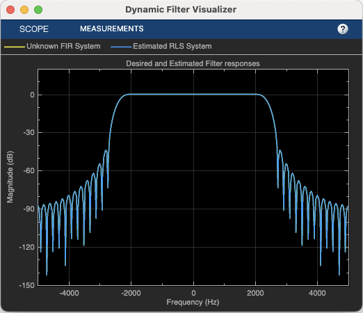
System Identification Using RLS Adaptive Filtering
Use a recursive least-squares (RLS) filter to identify an unknown system modeled with a lowpass FIR filter. Use the dynamic filter visualizer to compare the frequency response of the unknown and estimated systems. This example allows you to dynamically tune key simulation parameters using a user interface (UI). The example also shows you how to use MATLAB Coder™ to generate code for the algorithm and accelerate the speed of its execution.
Ports
Input
Specify the data input as a vector or a matrix. The block treats each column of the input signal as a separate channel. If the input is a two-dimensional signal, the first dimension represents the channel length (or frame size) and the second dimension represents the number of channels. If the input is a one-dimensional signal, then the block interprets it as having a single channel.
The block accepts variable-size input signals, that is, you can change the size of each input channel during simulation but you cannot change the number of channels.
This port is unnamed until you select one of these parameters:
Specify cutoff frequency from input port
Specify center frequency from input port
Specify bandwidth from input port
Data Types: single | double
Complex Number Support: Yes
Specify the cutoff frequency of the FIR filter as a real positive scalar in Hz or in normalized frequency units (since R2023a).
Dependencies
To enable this port, select the Specify cutoff frequency from input port parameter.
Data Types: single | double
Specify the center frequency of the FIR filter as a real positive scalar in Hz or in normalized frequency units (since R2023a).
Dependencies
To enable this port, select the Specify center frequency from input port parameter.
Data Types: single | double
Specify the bandwidth of the FIR filter as a real positive scalar in Hz or in normalized frequency units (since R2023a).
Dependencies
To enable this port, select the Specify bandwidth from input port parameter.
Data Types: single | double
Output
Filtered output, returned as a vector or a matrix. The size, data type, and complexity of the output signal matches that of the input signal.
Data Types: single | double
Complex Number Support: Yes
Parameters
Specify the order of the FIR filter as a positive integer scalar.
Specify the type of FIR filter. You can set this parameter to:
LowpassHighpassBandpassBandstop
When you select this check box, specify the cutoff frequency through the Fcut port. When you clear this check box, specify the cutoff frequency in the block dialog box through the Filter cutoff frequency parameter.
Dependency
To enable this parameter, set Filter type to
Lowpass or
Highpass.
Specify the cutoff frequency of the FIR filter as a real positive scalar in Hz or in normalized frequency units (since R2023a).
If you set the Sample rate mode parameter to:
Specify on dialogorInherit from input port— The value of the filter cutoff frequency is in Hz and must be less than half the value of the input sample rate.Use normalized frequency (0 to 1)— The value of the filter cutoff frequency is in normalized frequency units. The value must be a positive scalar less than1.0.
(since R2023a)
Tunable: Yes
Dependencies
To enable this parameter:
Set Filter type to
LowpassorHighpass.Clear the Specify cutoff frequency from input port parameter.
When you select this check box, specify the center frequency through the Fc port. When you clear this check box, specify the center frequency in the block dialog box through the Filter center frequency parameter.
Dependencies
To enable this parameter, set Filter type to
Bandpass or
Bandstop.
Specify the center frequency of the FIR filter as a real positive scalar in Hz or in normalized frequency units (since R2023a).
If you set the Sample rate mode parameter to:
Specify on dialogorInherit from input port— The value of the filter center frequency is in Hz and must be less than half the value of the input sample rate.Use normalized frequency (0 to 1)— The value of the filter center frequency is in normalized frequency units. The value must be a positive scalar less than1.0.
(since R2023a)
Tunable: Yes
Dependencies
To enable this parameter:
Set Filter type to
BandpassorBandstop.Clear the Specify center frequency from input port parameter.
When you select this check box, specify the filter bandwidth through the BW port. When you clear this check box, specify the filter bandwidth in the block dialog box through the Filter bandwidth parameter.
Dependency
To enable this parameter, set Filter type to
Bandpass or
Bandstop.
Specify the bandwidth of the FIR filter as a real positive scalar in Hz or in normalized frequency units (since R2023a).
If you set the Sample rate mode parameter to:
Specify on dialogorInherit from input port— The value of the filter bandwidth is in Hz and must be less than half the value of the input sample rate.Use normalized frequency (0 to 1)— The value of the filter bandwidth is in normalized frequency units. The value must be a positive scalar less than1.0.
(since R2023a)
Tunable: Yes
Dependencies
To enable this parameter:
Set Filter type to
BandpassorBandstop.Clear the Specify bandwidth from input port parameter.
Specify the window function used to design the FIR filter. You can set this parameter to:
HannHammingChebyshevKaiser
Specify the sidelobe attenuation of the Chebyshev window as a real positive scalar.
Dependencies
To enable this parameter, set Window function to
Chebyshev.
Specify the Kaiser window parameter as a real scalar.
Dependencies
To enable this parameter, set Window function to
Kaiser.
Since R2023a
Specify the input sample rate using one of these options:
Use normalized frequency (0 to 1)— Specify the filter cutoff frequency, center frequency, and the filter bandwidth in normalized frequency units (0 to 1).Specify on dialog— Specify the input sample rate in the block dialog box using the Input sample rate (Hz) parameter.Inherit from input port— The block inherits the sample rate from the input signal as N / Ts, where N is the frame size of the input signal and Ts is the sample time of the input signal.
Specify the sample rate of the input signal as a positive scalar in Hz.
Dependencies
To enable this parameter, set
the Sample rate mode parameter to
Specify on dialog. (since R2023a)
Clicking this button opens the filter visualizer and displays the magnitude response of the variable bandwidth FIR filter. The response is based on the parameters you select in the block dialog box. To update the magnitude response while the filter visualizer is running, modify the parameters in the dialog box and click Apply.
You can configure the plot settings and the signal measurements from the interface of the visualizer.
On the Scope tab of the filter visualizer toolstrip, the Configuration section allows you to modify the plot settings. On the Measurements tab, you can measure the signal statistics, place data cursors, and display the peak values of the selected signal.
For more details on the filter visualizer interface and its tools, see Configure Filter Visualizer.
Dependencies
To enable this button, do not specify any filter specifications from the input port.
Specify the type of simulation to run. You can set this parameter to:
Interpreted execution— Simulate model using the MATLAB® interpreter. This option shortens startup time.Code generation— Simulate model using generated C code. The first time you run a simulation, Simulink® generates C code for the block. The C code is reused for subsequent simulations as long as the model does not change. This option requires additional startup time but provides faster subsequent simulations.
Block Characteristics
Data Types |
|
Multidimensional Signals |
|
Variable-Size Signals |
|
Algorithms
All transformations assume a lowpass filter of length 2N+1.
Consider an ideal lowpass brickwall filter with normalized cutoff frequency ωc1. By taking the inverse discrete Fourier transform of the ideal frequency response, and clipping the resulting sequence to length 2N+1, the impulse response is:
where w(n) is the window vector. Tune the lowpass filter coefficients to a new cutoff frequency ωc2 as follows:
You do not need to recompute the window every time you tune the cutoff frequency.
Assuming a lowpass filter with normalized 6-dB cutoff frequency ωc, you can obtain a highpass filter with the same cutoff frequency by taking the complementary of the lowpass frequency response: HHP(ejω) = 1 − HLP(ejω)
Taking the inverse discrete Fourier transform of the above response, you have the following highpass filter coefficients:
Obtain a bandpass filter centered at frequency ω0 by shifting the lowpass response:
HBP(ejω) = HLP(ej(ω–ω0)) + HLP(ej(ω–ω0))
The bandwidth of the resulting bandpass filter is 2ωc, as measured between the two cutoff frequencies of the bandpass filter. The equivalent bandpass filter coefficients are then:
You can transform a lowpass filter to a bandstop filter by combining the highpass and bandpass transformations. First make the filter bandpass by shifting the lowpass response, and then invert it to get a bandstop response centered at ω0.
HBS(ejω) = 1 – (HLP(ej(ω–ω0)) + HLP(ej(ω+ω0)))
This yields the following coefficients:
You can combine these transformations to transform a lowpass filter to a lowpass, highpass, bandpass, or bandstop filter with arbitrary cutoffs.
For example, to transform a lowpass filter with cutoff ωc1 to a highpass with cutoff ωc2, you first apply the lowpass-to-lowpass transformation to get a lowpass filter with cutoff ωc2, and then apply the lowpass-to-highpass transformation to get the highpass with cutoff ωc2.
To get a bandpass filter with center frequency ω0 and bandwidth β, we first apply the lowpass-to-lowpass transformation to go from a lowpass with cutoff ωc to a lowpass with cutoff β/2, and then apply the lowpass-to-bandpass transformation to get the desired bandpass filter. You can use the same approach for a bandstop filter.
References
[1] Jarske, P., Y. Neuvo, and S. K. Mitra. "A Simple Approach to the Design of Linear Phase FIR Digital Filters with Variable Characteristics." Signal Processing 14, no. 4 *(1988): 313-326.
Extended Capabilities
The Variable Bandwidth FIR Filter block supports SIMD code generation using
Intel® AVX2 code replacement library when the input signal has a data type of
single or double.
The SIMD technology significantly improves the performance of the generated code. For more information, see SIMD Code Generation. To generate SIMD code from this block, see Use Intel AVX2 Code Replacement Library to Generate SIMD Code from Simulink Blocks.
Version History
Introduced in R2015aThe default value of the Simulate using parameter is now
Interpreted execution. With this change, the block uses the
MATLAB interpreter for simulation by default.
When you set the Sample rate mode parameter to
Use normalized frequency (0 to 1), you can specify
the filter cutoff frequency, center frequency, and filter bandwidth in normalized
frequency units (0 to 1).
MATLAB Command
You clicked a link that corresponds to this MATLAB command:
Run the command by entering it in the MATLAB Command Window. Web browsers do not support MATLAB commands.
Select a Web Site
Choose a web site to get translated content where available and see local events and offers. Based on your location, we recommend that you select: .
You can also select a web site from the following list
How to Get Best Site Performance
Select the China site (in Chinese or English) for best site performance. Other MathWorks country sites are not optimized for visits from your location.
Americas
- América Latina (Español)
- Canada (English)
- United States (English)
Europe
- Belgium (English)
- Denmark (English)
- Deutschland (Deutsch)
- España (Español)
- Finland (English)
- France (Français)
- Ireland (English)
- Italia (Italiano)
- Luxembourg (English)
- Netherlands (English)
- Norway (English)
- Österreich (Deutsch)
- Portugal (English)
- Sweden (English)
- Switzerland
- United Kingdom (English)