dsp.VariableBandwidthIIRFilter
Variable bandwidth IIR filter
Description
The dsp.VariableBandwidthIIRFilter object filters each channel of the
input using IIR filter implementations. It does so while having the capability of tuning the
bandwidth.
To filter each channel of the input:
Create the
dsp.VariableBandwidthIIRFilterobject and set its properties.Call the object with arguments, as if it were a function.
To learn more about how System objects work, see What Are System Objects?
Creation
Syntax
Description
vbwIIR = dsp.VariableBandwidthIIRFilter
vbwIIR = dsp.VariableBandwidthIIRFilter(PropertyName=Value)Name=Value pair arguments. Name is the
property name and Value is the corresponding value. For example,
PassbandFrequency=512 sets the passband frequency to 512 Hz.
Properties
Usage
Syntax
Description
y = vbwIIR(x)x using a variable bandwidth IIR
filter to produce the output y. The variable bandwidth IIR filter
object operates on each channel, which means the object filters every column of the input
signal independently over successive calls to the algorithm.
Input Arguments
Output Arguments
Object Functions
To use an object function, specify the
System object as the first input argument. For
example, to release system resources of a System object named obj, use
this syntax:
release(obj)
Examples
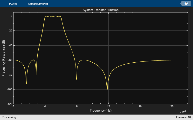
Tune the center frequency and the bandwidth of the IIR bandpass filter. Filter a sinusoidal signal through this filter.
Define a bandpass variable bandwidth IIR filter. Specify an input sample rate of 44100 Hz. Initialize a dsp.TransferFunctionEstimator object to estimate the transfer function of the filter from the input and output signals. To visualize the transfer function, initialize a dsp.ArrayPlot object.
Fs = 44100;
vbwiir = dsp.VariableBandwidthIIRFilter(FilterType='Bandpass',...
    FilterOrder=8,...
    SampleRate=Fs,...
    CenterFrequency=1e4,...
    Bandwidth=4e3);
tfe = dsp.TransferFunctionEstimator(FrequencyRange='onesided');
aplot = dsp.ArrayPlot(PlotType='Line',...
    XOffset=0,...
    YLimits=[-120 5], ...
    SampleIncrement=44100/1024,...
    YLabel='Frequency Response (dB)',...
    XLabel='Frequency (Hz)',...
    Title='System Transfer Function');
Generate a sine wave signal with a frame length of 1024. Tune the bandwidth and the center frequency of the filter. Pass the signal through this filter. Estimate the transfer function of the filter using the input and the generated output. Plot the system transfer function on Array Plot.
FrameLength = 1024;
sine = dsp.SineWave(SamplesPerFrame=FrameLength);
for i = 1:500
    % Generate input
    x = sine() + randn(FrameLength,1);
    % Pass input through the filter
    y = vbwiir(x);
    % Transfer function estimation
    h = tfe(x,y);
    % plot transfer function
    aplot(20*log10(abs(h)))
    % Tune bandwidth and center frequency of the IIR filter
    if (i==250)
        vbwiir.CenterFrequency = 5000;
        vbwiir.Bandwidth = 2000;
    end
end
Algorithms
This filter covers frequency transformations. The algorithm designs a lowpass IIR prototype
using the elliptical method by specifying its order, passband frequency, passband ripple,
and stopband attenuation. The passband ripple and stopband attenuation are equal to the
values of the PassbandRipple and StopbandAttenuation
properties. The algorithm sets the prototype passband frequency to 0.5. If the
FilterType property is 'Lowpass' or
'Highpass', the order of the prototype filter is equal to the value
of FilterOrder. If the FilterType property is
'Bandpass' or 'Bandstop', the order of the
prototype filter is equal to FilterOrder/2. The prototype is a Direct
Form II Transposed cascade of second-order sections (Biquad filter). The prototype is
transformed into the desired filter using the algorithms used in Digital Frequency Transformations. Each prototype SOS section is transformed
separately. When FilterType is 'Lowpass' or
'Highpass', the resulting filter remains a Direct Form II Transposed
cascade of second order sections. If the FilterType is
'Bandpass' or 'Bandstop', the resulting filter is
a cascade of Direct Form II Transposed cascade of fourth order sections.
References
[1] A. G. Constantinides. “Spectral transformations for digital filters”, Proc. Inst. Elect. Eng. Vol. 117, No. 8, 1970, pp. 1585-1590.
Extended Capabilities
Version History
Introduced in R2014aSee Also
Functions
freqz|filterAnalyzer|impz|info|coeffs|cost|grpdelay|outputDelay|setInputSampleRate