Two-Channel Filter Bank Using Halfband Decimators and Halfband Interpolators
A two-channel filter bank is a special case of the generic M-channel filter bank, where there are two filter branches. Implement the analysis portion of the filter bank using halfband decimators. Implement the synthesis portion of the filter bank using halfband interpolators.
These features implement the halfband decimators and halfband interpolators in DSP System Toolbox™.
dsp.FIRHalfbandDecimatorand FIR Halfband Decimator: Implement the analysis portion of the filter bank by using the FIR halfband filter.dsp.IIRHalfbandDecimatorand IIR Halfband Decimator: Implement the analysis portion of the filter bank by using the IIR halfband filter.dsp.FIRHalfbandInterpolatorand FIR Halfband Interpolator: Implement the synthesis portion of the filter bank by using the FIR halfband filter.dsp.IIRHalfbandInterpolatorand IIR Halfband Interpolator: Implement the synthesis portion of the filter bank by using the IIR halfband filter.
The two-channel analysis filter bank accepts a broadband signal as the input and splits this signal into lowpass and highpass subband signals. The two-channel synthesis filter bank accepts the lowpass and highpass subband signals as inputs and reconstructs the broadband signal using these two subbands.
Use either the FIR halfband or IIR halfband filters in the filter bank. Each filter has its own advantages and disadvantages and your choice should depend on the computational requirements of the application. IIR filters require fewer coefficients than FIR filters to execute similar filtering operations. IIR filters work faster and require less memory space. However, FIR filters are always stable. When the coefficients of an FIR filter are symmetric or anti-symmetric, the filter exhibits linear phase response.
Use an audio file input and compare the power spectrum of the filter bank output with that of the input signal. Then compare the cost of implementing both the FIR and IIR halfband filter banks.
Note: The audioDeviceWriter System object™ is not supported in MATLAB Online.
FIR Halfband Two-Channel Filter Bank
Set up the audio file reader and device writer. Create the FIR halfband decimator and interpolator to design a minimum order filter with a transition width of 2000 Hz and a stopband attenuation of 80 dB. Finally, set up the spectrum analyzer to display the power spectra of the filter bank input and output.
AF = dsp.AudioFileReader('speech_dft.mp3','SamplesPerFrame',1024);
AP = audioDeviceWriter('SampleRate',AF.SampleRate);

filterspec = 'Transition width and stopband attenuation';
TW = 2000;
Astop = 80;

firhalfbanddecim = dsp.FIRHalfbandDecimator(...
    'Specification',filterspec, ...
    'StopbandAttenuation',Astop,...
    'TransitionWidth',TW, ...
    'SampleRate',AF.SampleRate);

firhalfbandinterp = dsp.FIRHalfbandInterpolator(...
    'Specification',filterspec, ...
    'StopbandAttenuation',Astop,...
    'TransitionWidth',TW, ...
    'SampleRate',AF.SampleRate/2,...
    'FilterBankInputPort',true);

SpecAna = spectrumAnalyzer('SampleRate',AF.SampleRate,...
    'PlotAsTwoSidedSpectrum',false,...
    'ShowLegend',true,...
    'ChannelNames',{'Input signal','Filtered output signal'});
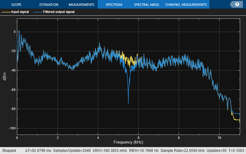
Read the audio 1024 samples at a time. Filter the input to obtain the lowpass and highpass subband signals decimated by a factor of two. This is the analysis portion of the filter bank. Use the FIR halfband interpolator as the synthesis filter bank. Display the running power spectrum of the audio input and the output of the synthesis filter bank. Play the output using the audio device writer.
while ~isDone(AF)
    audioInput = AF();
    [xlo,xhigh] = firhalfbanddecim(audioInput);
    audioOutput = firhalfbandinterp(xlo,xhigh);
    spectrumInput = [audioInput audioOutput];
    SpecAna(spectrumInput);
    AP(audioOutput);
end

release(AF);
release(AP);
release(SpecAna);
IIR Halfband Two-Channel Filter Bank
Set up the IIR halfband decimator and interpolator. The filters are of minimum order, have a transition width of 2000 Hz, and a stopband attenuation of 80 dB. Set up the spectrum analyzer to display the power spectra of the filter bank input and the output.
AF = dsp.AudioFileReader('speech_dft.mp3','SamplesPerFrame',1024);
AP = audioDeviceWriter('SampleRate',AF.SampleRate);

filterspec = 'Transition width and stopband attenuation';
TW = 2000;
Astop = 80;

iirhalfbanddecim = dsp.IIRHalfbandDecimator(...
    'Specification',filterspec,'StopbandAttenuation',Astop,...
    'TransitionWidth',TW,'SampleRate',AF.SampleRate);

iirhalfbandinterp = dsp.IIRHalfbandInterpolator(...
    'Specification',filterspec,'StopbandAttenuation',Astop,...
    'TransitionWidth',TW,'SampleRate',AF.SampleRate/2,...
    'FilterBankInputPort',true);

SpecAna = spectrumAnalyzer('SampleRate',AF.SampleRate,...
    'PlotAsTwoSidedSpectrum',false,...
    'ShowLegend',true,...
    'ChannelNames',{'Input signal','Filtered output signal'});
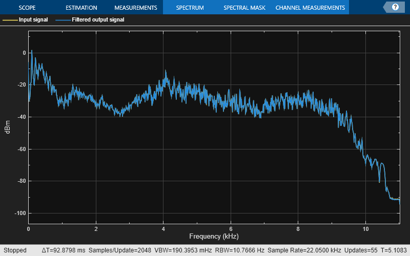
Read the audio 1024 samples at a time. Filter the input signal to obtain the lowpass and highpass subband signals decimated by a factor of two. This is the analysis portion of the filter bank. Use the IIR halfband interpolator as the synthesis filter bank. Display the running power spectrum of the audio input and the output of the synthesis filter bank. Play the output using the audio device writer.
while ~isDone(AF)
    audioInput = AF();
    [xlo,xhigh] = iirhalfbanddecim(audioInput);
    audioOutput = iirhalfbandinterp(xlo,xhigh);
    spectrumInput = [audioInput audioOutput];
    SpecAna(spectrumInput);
    AP(audioOutput);
end

release(AF);
release(AP);
release(SpecAna);
Compare the Cost
Compare the cost of implementing the FIR and IIR halfband decimators using the cost function. You can see that IIR halfband decimator is computationally more efficient.
cost(firhalfbanddecim)
ans = struct with fields:
                  NumCoefficients: 29
                        NumStates: 54
    MultiplicationsPerInputSample: 14.5000
          AdditionsPerInputSample: 14
cost(iirhalfbanddecim)
ans = struct with fields:
                  NumCoefficients: 5
                        NumStates: 7
    MultiplicationsPerInputSample: 2.5000
          AdditionsPerInputSample: 5
Compare the cost of implementing the FIR and IIR halfband interpolators. Again, the computational cost of implementing the IIR halfband interpolator is much less compared to the computational cost of implementing the IIR halfband decimator.
cost(firhalfbandinterp)
ans = struct with fields:
                  NumCoefficients: 28
                        NumStates: 27
    MultiplicationsPerInputSample: 28
          AdditionsPerInputSample: 27
cost(iirhalfbandinterp)
ans = struct with fields:
                  NumCoefficients: 5
                        NumStates: 7
    MultiplicationsPerInputSample: 5
          AdditionsPerInputSample: 10
Compare the Group Delay
You can also compare the group delay of the FIR and the IIR halfband filters.
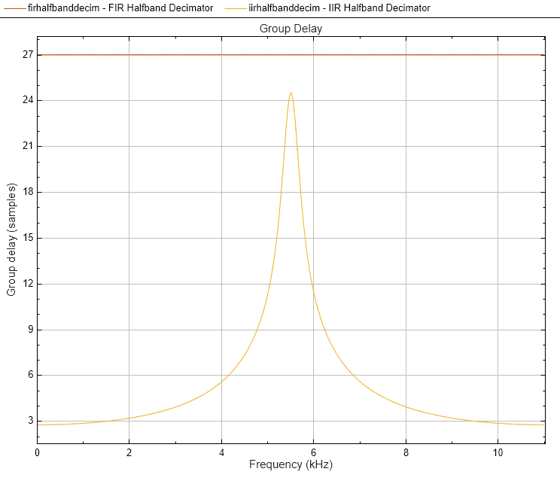
Display the group delay response of the FIR halfband and IIR halfband filters in the decimator. The FIR halfband filter has a linear phase response with a group delay of 25 samples. The IIR halfband filter has a nonlinear phase response, especially around the cutoff frequency of the filter. A constant group delay ensures that all the frequency components are delayed by the same amount.
h = filterAnalyzer(firhalfbanddecim,iirhalfbanddecim,'Analysis','groupdelay');
setLegendStrings(h,["FIR Halfband Decimator","IIR Halfband Decimator"])
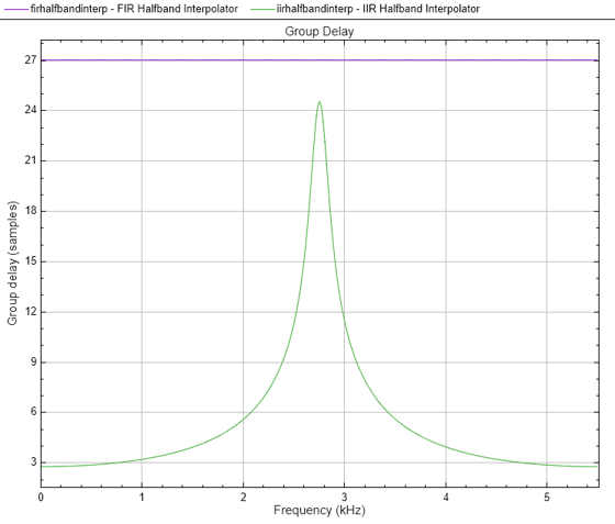
Similarly in the interpolator, the FIR halfband filter has a linear phase response, while the IIR halfband filter has a nonlinear phase response.
h = filterAnalyzer(firhalfbandinterp,iirhalfbandinterp,'Analysis','groupdelay');
setLegendStrings(h,["FIR Halfband Interpolator","IIR Halfband Interpolator"])
See Also
Objects
dsp.AudioFileReader|audioDeviceWriter|dsp.FIRHalfbandDecimator|dsp.FIRHalfbandInterpolator|dsp.IIRHalfbandDecimator|dsp.IIRHalfbandInterpolator