Model Configuration Parameters
R2026bModel configuration parameters control model behaviour, simulation, code optimizations, interfaces, code style, build options, and other aspects of the generated code. When you create a new model, it contains the default configuration set that specifies the default values for the model configuration parameters. You can view and update the configuration parameters by following these steps.
In the Simulink® Editor, press Ctrl+E or click Modeling > Model Settings to open Configuration Parameters dialog box.

In the Configuration Parameter dialog box, click Hardware Implementationto view the corresponding parameters.
Set the Hardware board parameter to
Infineon AURIX TC4x.Simulink automatically populates the parameter values under Hardware board settings to their default values. You can optionally adjust these parameters for your particular use case.
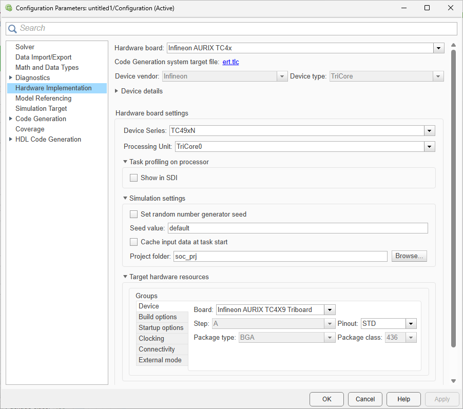
To apply the changes, click Apply.
Hardware board settings
| Parameter | Description | Default Value |
|---|---|---|
| Device Series | Device series for the selected hardware board. |
|
| Processing Unit | Processing unit to build and deploy the application model. | TriCore0 |
Simulation settings
| Parameter | Description | Default Value |
|---|---|---|
| Set random number generator seed | Set the random number generator seed. |
|
| Seed value | Specify the seed value for random number generator. | default |
| Cache input data at task start | Cache the input data at the start of a task. |
|
| Project folder | Select project folder to store generated code and executables | soc_prj |
Task profiling on processor
| Parameter | Description | Default Value |
|---|---|---|
| Show in SDI | Show the task execution data collected on hardware in the Simulation Data Inspector application. | off |
| Save to file | Save task execution data to a file | off |
| Overwrite file | Overwrite last task execution data file | off |
Target hardware resources
Device
| Parameter | Description | Default Value |
|---|---|---|
| Board | Hardware board of the selected device series | Infineon AURIX TC4X9
Triboard |
| Step | Displays the device step for the selected hardware board. |
|
| Pinout | Displays the pinout type for the selected hardware board. You can set the package class to STD or COM. |
|
| Package type | Displays the device packaging type for the selected hardware. |
|
| Package class | Displays the number of programmable pins for the selected hardware board/microcontrollers. |
|
| Pre-load TriCore0 with custom executable which enables current processing unit | Select to pre-load TriCore 0 with custom executable file to enable current processing unit. | off |
| Executable file for TriCore0 | The path to the custom executable file for TriCore 0 processing unit | $(AURIX_TC4XX_SHARED_ROOT_DIR)\TriCore0Executables\TC49x\TriCore0ExecutableToEnableTriCore#.hex |
Build Options
| Parameter | Description | Default Value |
|---|---|---|
| Build action | Define how Embedded Coder® responds when you build your model. |
|
| Disable parallel build | Select to compile the generated code and driver source codes in parallel order for faster build and deployment speed. | off |
| Enable force rebuild of static library | Select to force rebuild of the static driver library. |
|
| Use custom TCF file | Select this option to provide custom target configuration file (TCF) file for the parallel processing unit (PPU). | off |
| TCF file | The path to the memory description file required during linking. | $(MW_SYNOPSYSMWDT_ROOT_PATH)\config\set\TC49A_PPU\arc.tcf |
| Use custom linker file | Indicates that the custom linker command file must be used during the build action. |
|
| Linker file | The path to the memory description file required during linking. | $(AURIX_TC4XPPU_SHARED_ROOT_DIR)\src\TC49x\Lcf_Metaware_ArcEV_Ppu.lsl |
Startup options
| Parameter | Description | Default Value |
|---|---|---|
| Use custom startup | Select to execute custom initialization code when the microcontroller boots up |
|
| Startup code location | The file path for the initialization code when the microcontroller boots up |
|
| Use custom linker file | Indicates that the custom linker command file must be used during the build action. |
|
| Linker file | The path to the memory description file required during linking. | $(AURIX_TC4XX_SHARED_ROOT_DIR)\lib\tasking\tc49x\Lcf_Tasking_Tricore_Tc0.lsl |
| Boot From | Option to specify if the application has to load to the RAM or ROM. |
|
| Enable program cache | Select the program cache. |
|
| Enable data cache | Select the data cache. |
|
| Enable TriCore# | Select the TriCore #. |
|
| Enable PPU | Select the parallel processing unit (PPU) |
|
Clocking
| Parameter | Description | Default Value |
|---|---|---|
| External oscillator (MHz) | Oscillator frequency used in the processor. |
|
| CPU clock (MHz) | CPU clock frequency of the microcontrollers on the target hardware |
|
| PPU clock (MHz) | PPU clock frequency of the microcontrollers on the target hardware | 400 |
Connectivity
| Parameter | Description | Default Value |
|---|---|---|
| Connectivity interface | Select the type of connectivity interface for PIL or external mode simulation. | Serial (ASCLIN0) |
| Node | Specify controller area network (CAN) node for universal measurement and calibration protocol (XCP)-based external mode simulation over CAN. | 0 |
| Serial port in MATLAB preferences | Select the serial communication interface module. | empty |
| Baud rate | Select the baud rate for the processor-in-loop (PIL) or external mode simulation. | 921600 |
| Tx Pin | Select the transmission pin number for serial or CAN communication. | P14_0 |
| Rx Pin | Select the reception pin number for serial or CAN communication. | P14_1 |
| CAN Vendor | Specify CAN vendor for XCP over CAN through which the host computer communicates with the target hardware for external mode simulation. | <empty> |
| CAN Device | Specify CAN device for XCP-based external mode simulation over CAN. | <empty> |
| CAN Channel | Specify the vendor-specific CAN channel used for XCP-based external mode simulation over CAN. | <empty> |
| Extended CAN ID | Select to enable extend CAN ID for XCP-based external mode simulation over complex CAN networks. | off |
| CAN ID command | Specify the CAN identifier used by the host computer to transmit command or request messages to a CAN node. | 2 |
| CAN ID response | Specify the CAN identifier used by the CAN node to send response or status messages to the host computer. | 3 |
External mode
| Parameter | Description | Default Value |
|---|---|---|
| Communication interface | Select the transport layer that external mode simulation uses to exchange data between the host computer and the target hardware. | Serial |
| Port | Specify the port number for XCP-based external mode simulation over transmission control protocol/internet protocol (TCP/IP). | 17725 |
| Host interface | Select the host computer through which the host computer communicates to Infineon AURIX microcontroller for signal monitoring and parameter tuning. | Simulink |
| Verbose | Select to view the external mode simulation progress and updates. | off |
| Set logging buffer size automatically | Select to automatically set the number of bytes to preallocate for the buffer in the hardware during simulation. | on |
| Logging buffer size (in bytes) | Specify the memory buffer size for XCP-based external mode simulation. | 2000 |
For more information on selecting a hardware board and general configuration settings, see Hardware Implementation Pane.

