PIL Simulation for AUTOSAR Software Component with Infineon AURIX TC4x Microcontrollers
This example shows how to use Embedded Coder® Support Package for Infineon AURIX™ TC4x Microcontrollers for code verification and validation of AUTOSAR component models using PIL. This example uses Simulink® models with Infineon AURIX TC4x TriBoards mapped to a classic AUTOSAR software component, generating code that complies with the AUTOSAR standard.
In this example, you learn how to configure a Simulink® model for processor-in-the-loop (PIL) simulation and validate the generated code in two modeling scenarios: referenced model and top model. In a PIL simulation, the generated code runs on the TC4x TriBoards. The results of the PIL simulation are transferred to Simulink to verify the numerical equivalence of the simulation and the code generation results. This PIL verification process is a crucial part of the development cycle to ensure that the behavior of the deployment code matches the design.
Prerequisites
For more information on deploying a Simulink model to a hardware board, see Getting Started with Embedded Coder Support Package for Infineon AURIX TC4x Microcontrollers.
For more information on mapping a Simulink model to an AUTOSAR component, see Create AUTOSAR Software Component in Simulink (AUTOSAR Blockset).
Required Hardware
Infineon AURIX TC4x - TriBoards
Micro-USB cable
Choose Communication Interface for PIL Simulation
These steps choose a hardware resource to configure a Simulink model for PIL simulation.
1. Open a Simulink model that must be configured for PIL simulation. The models attached with this example are configured for Infineon AURIX TC4x hardware boards hardware with autosar.tlc code generation target file.
2. To run the model on other Infineon AURIX processors, you must configure the model with the hardware details. To configure the model, press Ctrl+E to open the Configuration Parameters dialog box and navigate to the Hardware Implementation tab. In this tab, select the required hardware board in Device details and Target hardware resources.
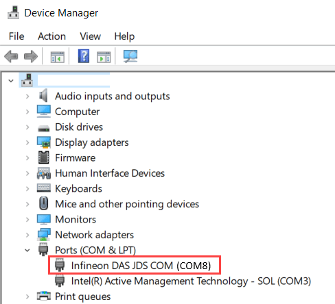
3. Navigate to Configuration Parameters > Hardware Implementation > Target Hardware Resources > Connectivity > Serial port in MATLAB preferences, select the COM port on the host computer for PIL simulations. This example uses the COM8 port because the Infineon DAS JDS COM board is connected to the host computer on this port. You can update the COM port number according to the port information available in the device manager of your host computer.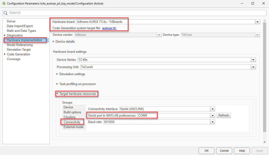
To find the COM port number of the USB Serial Port on your host computer, browse to Device Manager > Ports (COM & LPT) > Infineon DAS JDS COM to find the COM port.
Verify Referenced Model Code Using PIL
Before verifying the referenced model code, you must configure the model to load test vectors or stimulus inputs. You can configure the model either by adding a test harness model or by updating the PostLoadFcn Callback. In this example, the PostLoadFcn Callback configures the model to load stimulus inputs.
These steps verify the code generated by the reference model running in the PIL mode:
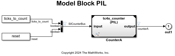
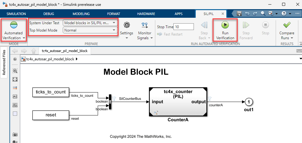
1. Open the tc4x_autosar_pil_model_block model.
This model contains a referenced model named CounterA. Double-click the referenced model to open the reference model tc4x_counter. You can configure the hardware board for the model by following the steps in the Choose Communication Interface for PIL Simulation section.
2. Choose the COM port.
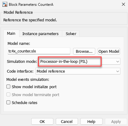
3. Configure and run CounterA Model block in PIL simulation mode.
Right-click
CounterAblock and select Block Parameters (ModelReference).Verify if Simulation mode is set to Processor-in-the-loop(PIL) and click OK.
4. Run tc4x_autosar_pil_model_block in PIL simulation.
Open the Apps tab and select SIL/PIL Manager.
On the SIL/PIL tab, verify if the Mode is set to Automated Verification and click Run Verification.
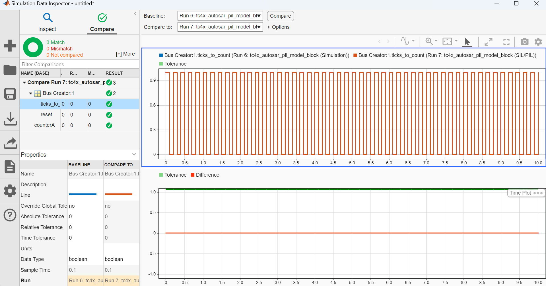
5. The SIL/PIL Manager application runs the model in normal and PIL simulation mode and launches the Simulation Data Inspector to compare the simulation results.
These plots compare the normal and PIL simulation metrics for the attached model tc4x_autosar_pil_model_block.
Verify Top Model Code Using PIL
Before verifying the top model code, you must configure the model to load test vectors or stimulus inputs from the MATLAB workspace. In this example, the PostLoadFcn Callback configures the model using the function defined in aurixAutosarPILTopmodelData.m to load stimulus inputs.
These steps verify the code generated by the top model running in the PIL mode:
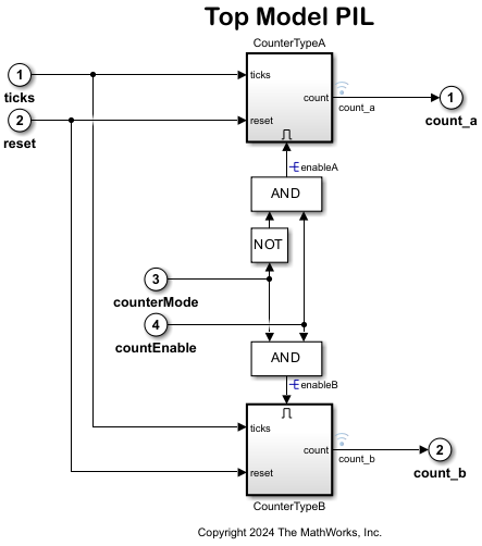
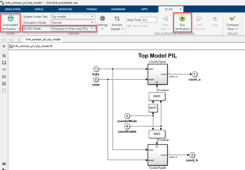
1. Open the tc4x_autosar_pil_top_model model.
2. Choose the COM port.
3. Run tc4x_autosar_pil_top_model in PIL simulation.
Open the Apps tab and select SIL/PIL Manager.
On the SIL/PIL tab, verify if the Mode is set to Automated Verification and the SIL/PIL Mode is set to Processor-in-the-loop(PIL). Click Run Verification.
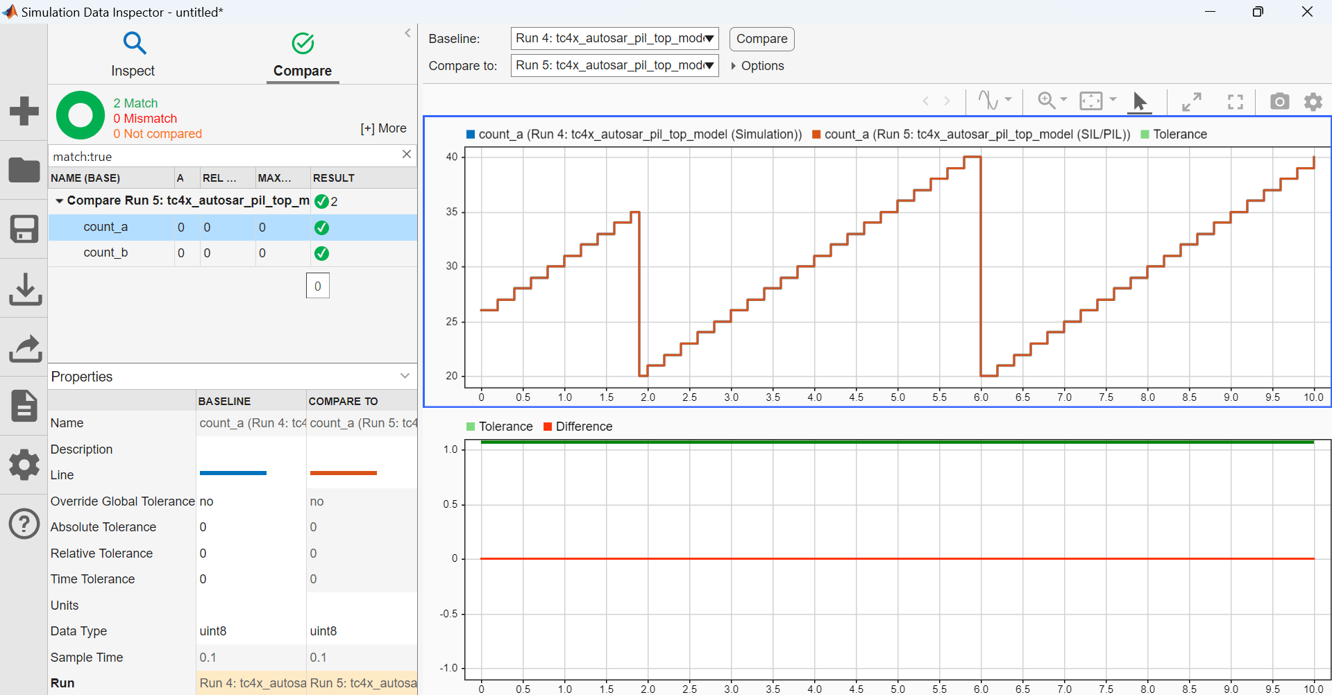
4. The SIL/PIL Manager application runs the model in normal and PIL simulation mode and launches the Simulation Data Inspector to compare the simulation results.
These plots compare the normal and PIL simulation metrics for the attached model tc4x_autosar_pil_top_model.
5. When the PIL simulation is completed, a logsOut variable is created in the base workspace. The logsOut data contains the PIL simulation results. You can access the logged data for signals count_a and count_b using the following commands:
count_a = get(logsOut,'count_a');count_a.Values.Datacount_b = get(logsOut,'count_b');count_b.Values.Data
Note: Infineon AURIX TC4x microcontrollers use an STM timer for PIL profiling.
See Also
Topics
- Create AUTOSAR Software Component in Simulink (AUTOSAR Blockset)
- Generate AUTOSAR C Code and XML Descriptions (AUTOSAR Blockset)
- Code Verification and Validation with PIL