Trace Stateflow Elements in Generated Code
To verify the generated code for your Stateflow® elements, you can trace Stateflow elements in your model to the generated code by using these types of navigation:
Code-to-model: Trace generated code back to the model by clicking hyperlinks in the comments or the hyperlinked line numbers, which highlights the corresponding model element in the Simulink Editor.
Model-to-code: Trace the model elements in the Simulink Editor to corresponding lines in generated code by right-clicking the model element and navigating to the generated code. This traceability is not supported for some Stateflow elements in Code view.
These examples illustrate how to trace different Stateflow elements.
Inline Traceability for Stateflow Elements
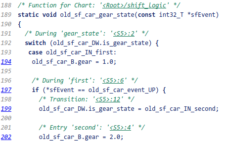
Inline traceability refers to the line-level traceability available in the generated code. You can click the hyper-linked line numbers to trace single or multiple Stateflow elements at the same time.
Open the model.
openExample('old_sf_car')Configure the model as an ERT target.
On the Code Generation > Report pane, select these model configuration parameters:
Select Code Generation > Comments > Stateflow object comments configuration parameter. This parameter enables the traceability comments for Stateflow elements.
Go to the Code Generation > Interface pane. In the Software environment section, select continuous time. Click Apply. Before generating code, you must perform this step because this model contains a block with a continuous sample time.
On the C Code tab, click Build.
After the code generation process is complete, the code generation report appears.
In the report, on the left navigation pane, click the
old_sf_car.chyperlink.To the view the inline traceability hyperlinks, scroll through the code. These line numbers can differ from the numbers that appear in your code generation report.

Click the hyperlink on line number
190. The corresponding element is highlighted.
Bidirectional Traceability for States and Transitions
Open the model.
openExample('old_sf_car')Complete steps 2 through 5 in Inline Traceability for Stateflow Elements.
Press Ctrl+B to generate source code and header files for the
old_sf_carmodel that contains theshift_logicchart. After the code generation process is complete, the code generation report appears.In the report, click the
old_sf_car.chyperlink.
View Results
To see the traceability comments, scroll through the code. These line numbers can differ from the numbers that appear in your code generation report.

Click the
<S5>:2hyperlink in this traceability comment:/* During 'gear_state': '<S5>:2' */The corresponding state appears highlighted in the chart.
Click the
<S5>:12hyperlink in this traceability comment:/* Transition: '<S5>:12' */The corresponding transition appears highlighted in the chart. To remove highlighting from an element in the chart, press the Esc key.
You can also trace elements in the model to lines of generated code. In the chart, right-click the element
gear_stateand select C/C++ Code > Navigate to C/C++ Code.The code for that state appears highlighted in
old_sf_car.c.
In the chart, right-click the transition with the condition
[speed >
                up_th]
and select C/C++ Code > Navigate to C/C++ Code.The code for that transition appears highlighted in
old_sf_car.c.
Note
For a list of the Stateflow elements in your model that are traceable, click the Traceability Report hyperlink in the code generation report.
Bidirectional Traceability for State Transition Tables
This example shows how to navigate bidirectionally between elements in a state transition table and the generated C/C++ and HDL code for traceability.
Open the model. This model is already configured for traceability.
openExample('sf_cdplayer_STT')Press Ctrl+B to generate source code and header files for the
sf_cdplayer_STTmodel. After the code generation process is complete, the code generation report appears.Click the
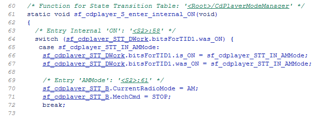
sf_cdplayer_STT.chyperlink in the report.To see the traceability comments, scroll through the code. The line numbers shown can differ from the numbers that appear in your code generation report.

Click the
<S2>:58hyperlink in this traceability comment:/* Entry Internal 'ON': '<S2>:58' */The corresponding state
'ON'appears highlighted in the state transition table.
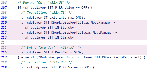
You can trace a state or transition from the state transition table to the generated code. Right-click the state
Standbyand select C/C++ Code > Navigate to C/C++ Code.The entry code for the state
Standbyis highlighted in the generated code.
Bidirectional Traceability for Truth Table Blocks
Open the model.
openExample('sf_climate_control')Complete steps 2 through 5 in Inline Traceability for Stateflow Elements.
To build the model, press Ctrl+B.
In the code generation report, click the
sf_climate_control.chyperlink.To see the traceability comments, scroll through the code. These line numbers can differ from the numbers that appear in your code.

Click the
<S1>:1:47hyperlink in this traceability comment:/* Action '3': '<S1>:1:47' */In the Truth Table Editor, row 3 of the Action Table appears highlighted.

You can also trace a condition, decision, or action in the table to a line of generated code. For example, right-click a cell in the column
D2and select C/C++ Code > Navigate to C/C++ Code.The code for that decision appears highlighted in
sf_climate_control.c.
Tip
To select C/C++ Code > Navigate to C/C++ Code for a condition, decision, or action, right-click a cell in the row or column that corresponds to that truth table element.
Bidirectional Traceability for Graphical Functions
Open the model.
openExample("stateflow/ClutchWithEnabledSubsystemsExample")Complete steps 2 through 5 in Inline Traceability for Stateflow Elements.
In the Configuration Parameters dialog box, go to the Solver pane. In the Solver selection section, select
Fixed-stepin the Type field. Click Apply. Before generating code, you must perform this step because the model does not work with variable-step solvers.To build the model, press Ctrl+B.
In the code generation report, click the
sf_clutch_enabled_subsystems.chyperlink.To see the traceability comments, scroll through the code. These line numbers can differ from the numbers that appear in your code generation report.

Click the
<S1>:3hyperlink in this traceability comment:/* Graphical Function 'getSlipTorque': '<S1>:3' */In the chart, the graphical function
getSlipTorqueappears highlighted.You can trace a graphical function in the chart to a line of generated code. For example, right-click the graphical function
detectSlipand select C/C++ Code > Navigate to C/C++ Code.The code for that graphical function appears highlighted in
sf_clutch_enabled_subsystems.c.
Code-to-Model Traceability for Events
Open the model.
openExample('stateflow/EdgeTriggeredEventExample')Complete steps 2 through 5 in Inline Traceability for Stateflow Elements.
To build the model, press Ctrl+B.
In the code generation report, click the
sf_loop_scheduler.chyperlink.To see this traceability comment, scroll through the code. These numbers can differ from the numbers that appear in your code generation report.

Click the
<S3>:12hyperlink in this traceability comment:/* Event: '<S3>:12' */In the Contents pane of the Model Explorer, the event
A1appears highlighted.
Model-to-Code Traceability for Junctions
Open the model.
openExample('ex_if_else_SF')Complete steps 2 through 5 in Inline Traceability for Stateflow Elements.
To build the model, press Ctrl+B.
In the code generation report, open the Stateflow chart named
Chart.Right-click the top-left junction and select C/C++ Code > Navigate to C/C++ Code.
The code for the first outgoing transition of that junction appears highlighted in
ex_if_else_SF.c.
Format of Traceability Comments for Stateflow Elements
The format of a traceability comment depends on the Stateflow element type.
State
Syntax
/* <ActionType> '<StateName>': '<elementHyperlink>' */Example
/* During 'gear_state': '<S5>:2' */This comment refers to the during action of the state
gear_state, which has the hyperlink
<S5>:2.
Transition
Syntax
/* Transition: '<elementHyperlink>' */Example
/* Transition: '<S5>:12' */This comment refers to a transition, which has the hyperlink
<S5>:12.
MATLAB Function
Syntax
/* MATLAB Function '<Name>': '<elementHyperlink>' */Within the inlined code for a MATLAB® function, comments that link to individual lines of the function have this syntax:
/* '<elementHyperlink>' */Examples
/* MATLAB Function 'test_function': '<S50>:99' */
/* '<S50>:99:20' */The first comment refers to the MATLAB function named test_function, which has the hyperlink
<S50>:99.
The second comment refers to line 20 of the MATLAB function in your chart.
Truth Table Block
Syntax
/* Truth Table Function '<Name>': '<elementHyperlink>' */
Within the inlined code for a Truth Table block, comments for conditions, decisions, and actions have this syntax:
/* Condition '#<Num>': '<elementHyperlink>' */
/* Decision 'D<Num>': '<elementHyperlink>' */
/* Action '<Num>': '<elementHyperlink>' */
<Num> is the row or column number that appears in the Truth
Table Editor.
Examples
/* Truth Table Function 'truth_table_default': '<S10>:100' */
/* Condition '#1': '<S10>:100:8' */
/* Decision 'D1': '<S10>:100:16' */
/* Action '1': '<S10>:100:31' */
The first comment refers to a Truth Table block named
truth_table_default, which has the hyperlink
<S10>:100.
The other three comments refer to elements of that Truth Table block. Each condition, decision, and action in the Truth Table block has a unique hyperlink.
Truth Table Function
For syntax and examples, see Truth Table Block.
Graphical Function
Syntax
/* Graphical Function '<Name>': '<elementHyperlink>' */Example
/* Graphical Function 'hello': '<S1>:123' */This comment refers to a graphical function named hello, which
has the hyperlink <S1>:123.
Simulink Function
Syntax
/* Simulink Function '<Name>': '<elementHyperlink>' */Example
/* Simulink Function 'simfcn': '<S4>:10' */This comment refers to a Simulink® function named simfcn, which has the hyperlink
<S4>:10.
Event
Syntax
/* Event: '<elementHyperlink>' */Example
/* Event: '<S3>:33' */This comment refers to an event, which has the hyperlink
<S3>:33.