Create Fault Tree Events
R2026bIn fault tree documents, events represent the starting point of a failure. To set the failure properties of an event, you create a failure model and assign it to the event. The type of failure model determines how the Safety Analysis Manager calculates the failure properties.
You can connect events directly to the top-level gate, or to intermediate gates in the tree. For more information on creating gates, see Create Fault Tree Gates.
Add Event to Fault Tree
To add an event to a fault tree:
Open the Safety Analysis Manager. In MATLAB® or Simulink®, in the Apps tab, click Safety Analysis Manager.
Create or open a fault tree document.
To create a new document, click New > Fault Tree Document.
To open an existing document, click Open and select the document.
Select a gate. New fault tree documents contain one fault tree, which contains only one top-level gate.
In the Tree section, click Basic and select the event type.
You can specify these event types:
| Event Type Symbol | Event Type | Description |
|---|---|---|
|
| Basic | The starting point of failure in the tree. |
|
| Undeveloped | Events whose contribution to the design is unknown. These events may require additional details or are trivial. |
|
| House | Events that either occur or do not occur. |
Create Unassigned Events
To add an event to a fault tree document without assigning it to a gate:
Open the Artifacts pane by clicking Artifacts at the bottom of the Safety Analysis Manager.
Set the drop-down list in the top-left corner to
Events.Click the Add new event button .
To assign the event to a gate, select a gate, click Basic > Existing Event, and select the event.
Create Shared Events
Shared events are events that you can use in multiple places in a fault tree document. To create a shared event:
Select a gate.
In the Tree section, click Basic > Existing Event. The Select Event dialog box opens.
Select the event in the Event Label list and click OK.
Copy Assigned Events
You can copy events and paste them to other gates. For more information, see Copy Fault Tree Artifacts.
Define Event Properties
When you select the event, the event properties display in the Properties pane.
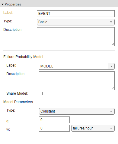
To change the event type, in the Properties pane, use the Type property. You can also specify the name and a description of the event by defining the Name and Description properties.
The fields in Failure Probability Model and Model Parameters sections define the failure model assigned to the event and its properties. To assign a failure model, use the Label property. Basic and undeveloped events use failure models to define two failure properties:
q — The unavailability of the event, also known as the failure probability. This property is unitless.
w — The failure frequency of the event, in failures per unit time.
The type of failure model determines how the fault tree calculates q and w. To set the failure model type, under Model Parameters, set the Type property. You can choose from constant, rate, time at risk, MTTF, dormant, or logical failure models. For additional details on how these failure models are calculated, see [1–5].
You can assign the failure model to more than one event. To share the failure model with other events, enable the Share Model property. In another event, select the failure probability model in the Name property.
Constant Failure Model
The constant failure model assumes that the unavailability and frequency are constant throughout the evaluation time. You explicitly define the values for q and w by using the q and w parameters.
This failure model is not available for house events.
Rate Failure Model
The rate failure model assumes that the failure rate is constant throughout time, that the failure unavailability has an exponential relationship with time, and that the failure is repairable. You specify these parameters:
λ — The failure rate. The default unit is failures per hour.
µ — The repair rate of the event. The default unit is repairs per hour.
The Safety Analysis Manager calculates q and w by using λ and µ in these equations:
where t represents the elapsed time. You specify t by setting the Mission Time property when you evaluate the fault tree document. For more information on evaluating fault trees, see Evaluate Fault Tree Documents.
This failure model is not available for house events.
Time at Risk Failure Model
The time at risk failure model assumes that the failure rate is constant throughout time, but that the failure unavailability has an exponential relationship with a specified exposure time. You specify these parameters:
λ — The failure rate. This metric is identical to λ in the rate failure model. The default unit is failures per hour.
trisk — The exposure time. The default unit is hours.
trisk is independent from the Mission Time property.
The Safety Analysis Manager calculates q and w by using λ and trisk in these equations:
This failure model is not available for house events.
Tip
If you want to use a time at risk failure model where
trisk equals the evaluation
time, use a rate model and set µ to
0.
MTTF Failure Model
The mean time to failure (MTTF) failure model assumes that you know how much time elapses before a failure occurs, and how much time elapses before the failure is fixed. You specify these parameters:
MTTF — The mean time to failure. The default unit is hours.
MTTR — The mean time to repair. The default unit is minutes.
The equations for q and w are the same as the rate failure model. MTTF equals 1/λ, and MTTR equals 1/µ.
This failure model is not available for house events.
Dormant Failure Model
The dormant failure model assumes that the failure occurs and remains in a failed state until the failure is inspected and then repaired. The parameters are constant throughout time. You specify these parameters:
τ — The inspection interval. For every unit of this parameter, an inspection occurs. The default unit is hours.
λ — The failure rate. This metric is identical to λ in the time at risk failure model. The default unit is failures per hour.
MTTR — The mean time to repair. This metric is identical to MTTR in the MTTF failure model. The default unit is minutes.
The Safety Analysis Manager calculates q and w by using τ, λ, and MTTR in these equations:
This failure model is not available for house events.
Logical Failure Model
The logical failure model represents a failure that is either active or not. Consequentially,
the event probability is either 1 or 0. You
can select one of these statuses:
Active — The event is active.
Inactive — The event is inactive.
Expression — The event activates when the specified MATLAB expression is
true. It is otherwise inactive.
Define Failure Model Parameter Values
You can define the parameter values for the failure model as scalar literals or by using
MATLAB expressions that evaluate to a scalar. When you define an expression, the
Safety Analysis Manager maps the variables to base workspace variables.
The output of the expression must match the data type and value range supported by the
parameter. Expressions in constant, rate, MTTF, and dormant failure models must return a
numeric scalar. Expressions in logical failure models must return a scalar logical
true or false.
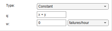
For example, suppose you have two variables, x and y,
that you define in the base workspace. To set the value of q for a
constant failure as the sum of the variables, enter x + y into
q.
View All Events and Failure Models
To view events and failure models for all of the events in the fault tree document, open the Artifacts pane.
To select an event, set the drop-down list in the top-left corner to
Events.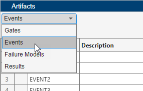
To view the location of an event in the fault tree, set the drop-down list to
Eventsand click the Highlight event in tree button .To select a failure model, set the drop-down list in the top-left corner to
Failure Models.
You can select multiple events or failure models by pressing Shift and clicking the artifacts. Selecting one event or failure model displays the properties in the Properties pane.
To filter the events or failure models, enter a term in the
Search box. You can use the drop-down list to filter the
results based on the specified property. For checkbox columns, enter
true or false to filter the results.
By default, the Artifacts pane lists the events by order of their creation. To sort the events alphabetically, point to the right side of a column and click. You can sort alphabetically in ascending or descending order.
View Gates That Use a Shared Event
To view the gates that use shared events:
Select the event in the fault tree or in the Artifacts pane.
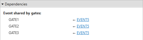
In the Properties pane, expand the Dependencies section.
The section displays each gate that uses the shared event.
View Events That Use a Failure Model
To view the events that use a specific failure model:
Select the failure model in the Artifacts pane.
In the Properties pane, expand the Dependencies section.
The section displays each event that uses the failure model.
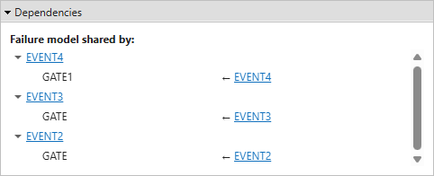
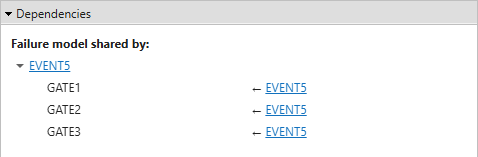
If the failure model is assigned to a shared event, the list displays each gate that uses the shared event.
References
[1] Kumamoto, Hiromitsu, and Ernest J. Henley. Probabilistic Risk Assessment and Management for Engineers and Scientists. 2nd ed. IEEE, 2000. https://doi.org/10.1109/9780470546277.
[2] MILITARY HANDBOOK ELECTRONIC RELIABILITY DESIGN HANDBOOK. U.S. Department of Defense, 1998. https://quicksearch.dla.mil/qsDocDetails.aspx?ident_number=54022.
[3] Nieuwhof, G.W.E. “An Introduction to Fault Tree Analysis with Emphasis on Failure Rate Evaluation.” Microelectronics Reliability 14, no. 2 (1975): 105–19. https://doi.org/10.1016/0026-2714(75)90024-4.
[4] Rauzy, Antoine. Probabilistic Safety Analysis with XFTA. The AltaRica Association, 2020.
[5] Vesely, W.E., F.F. Goldberg, N.H. Roberts, and D.F. Haasl. Fault Tree Handbook. U.S. Nuclear Regulatory Commission, 1981.

