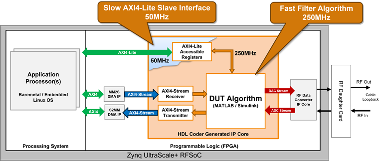
Enable Clock Domain Crossing on AXI4-Lite Interfaces
To transfer data between your IP core register interface and your design under test (DUT) in any of these scenarios:
IP core register interfaces operates at a lower frequency than the DUT
IP core register interface operates at a higher frequency than your DUT
IP core register interface and the DUT use asynchronous clocks
use clock domain crossing (CDC). To enable CDC, select the Enable clock domain crossing on AXI4-Lite registers setting in the Generate RTL Code and IP Core task in the HDL Workflow Advisor.
When you enable CDC, HDL Coder™ inserts CDC and back pressure logic that crosses the signals from the AXI4-Lite clock domain to the IP core clock domain, or from the IP core clock domain to the AXI4-Lite clock domain.
You must set your Synthesis Tool to Xilinx
Vivado to use CDC for the AXI4-Lite interface.
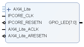
This image shows the generated IP core. When you enable CDC, you can connect different
clock signals to the IP core clock IPCORE_CLK and AXI4-Lite interface
clock AXI4_Lite_ACLK. When you disable CDC, you must connect the same
clock signal to the IP core clock and AXI4-Lite interface clock. For more information on how
to connect the clock signals, see Custom IP Core Generation.
When you export the HDL Workflow Advisor run to a script, you can observe the saved CDC
setting as a hdlset_param command. For example, if you enable the
setting on the DUT subsystem in the hdlcoder_led_vector model, you can
access the CDC setting by entering:
hdlset_param('hdlcoder_led_vector/DUT',...
ClockDomainCrossingOnregisterInterface,'on');
Clock domain crossing achieves the multi-bit data synchronization by using a pulse synchronizer and two multi-bit registers. The address decoder repeatedly uses this implementation to cross the signals to and from each clock domain. This image shows the architecture that the CDC implementation uses.
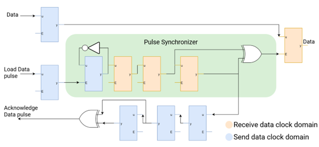
The additional CDC logic introduces latency and back pressure on the AXI4-Lite interface due to the added latency to the read and write operations. However, because the ARM® processor that accesses the AXI registers on the SoC boards has a larger latency, the introduced latency has minimal impact. In addition, there are no dependencies between the clock frequency for the DUT IP core and the AXI4-Lite clock frequency.
The synthesis tool requires timing constraints to analyze the paths in the CDC logic. HDL Coder generates these constraints and outputs them as a Xilinx Design Constraints (XDC) file and packages the file with the generated IP core.
To view the generated XDC file, use one of these methods:
Open the constraints file packaged inside the generated IP core project folder.
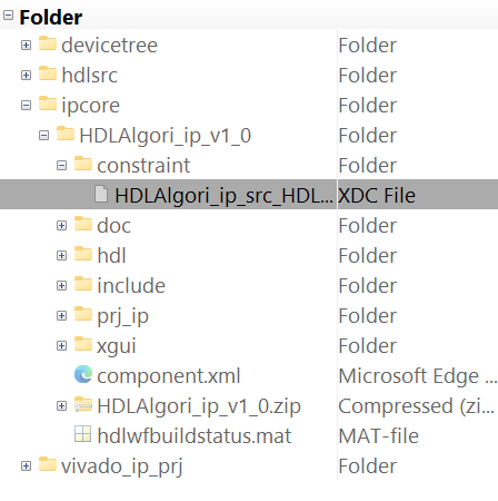
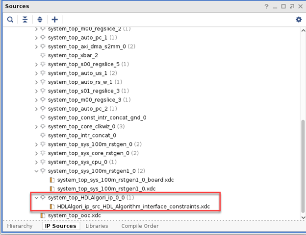
Open the Xilinx® Vivado® project after you generate a bitstream for your IP core. Open the Sources window, open the IP Sources tab, and navigate to the generated IP core folder.
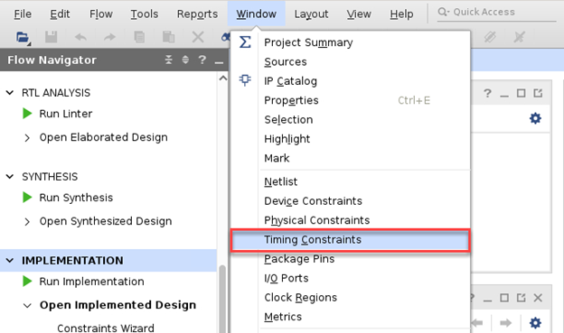
Open the Timing Constraints window in Xilinx Vivado.
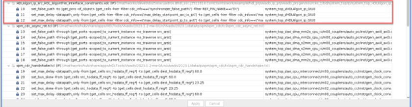
Inspect the constraints applied to the project to locate the clock domain crossing constraints.
This code snippet presents the XDC file generated for use with the Xilinx Vivado environment.
# AXI4-Lite CDC constraints:
set reg_axitoip [get_cells -hier -filter {hdlc_maxdelay=="clk_axitoip"}]
set clk_axitoip [get_clocks -of $reg_axitoip]
set clk_period_axitoip [get_property PERIOD $clk_axitoip]
set reg_iptoaxi [get_cells -hier -filter {hdlc_maxdelay=="clk_iptoaxi"}]
set clk_iptoaxi [get_clocks -of $reg_iptoaxi]
set clk_period_iptoaxi [get_property PERIOD $clk_iptoaxi]
set falsepathregcells [get_cells -hier -filter {hdlc_falsepath=="data"}]
set falsepathregpins [get_pins -of_objects $falsepathregcells -filter {REF_PIN_NAME=="D"}]
set_false_path -to $falsepathregpins
set startreglist_iptoaxi [get_cells -hier -filter {hdlc_maxdelay=="data_iptoaxi_start"}]
set endreglist_iptoaxi [get_cells -hier -filter {hdlc_maxdelay=="data_iptoaxi_end"}]
set_max_delay -from $startreglist_iptoaxi -to $endreglist_iptoaxi -datapath_only $clk_period_iptoaxi -quiet
set startreglist_axitoip [get_cells -hier -filter {hdlc_maxdelay=="data_axitoip_start"}]
set endreglist_axitoip [get_cells -hier -filter {hdlc_maxdelay=="data_axitoip_end"}]
set_max_delay -from $startreglist_axitoip -to $endreglist_axitoip -datapath_only $clk_period_axitoip -quiet
The HDL Coder generated constraints add maximum delay and false path constraints to sets of
registers that are part of the CDC synchronizing circuits. HDL Coder finds these registers by searching the synthesis netlist for the
hdlc_maxdelay ATTRIBUTE and hdlc_falsepath
ATTRIBUTE keywords. This approach is more reliable than just looking for
patterns in module or signal names. This code snippet shows an example of the use of the
hdlc_falsepath keyword in one of the address decoder modules
netlists:
...
ATTRIBUTE hdlc_falsepath : string;
…
ATTRIBUTE hdlc_falsepath OF s_level_2FlopSync1 : SIGNAL IS "data";
...