Map HDL FIFO Blocks to UltraRAM Resources on FPGA
This example shows how to configure an HDL FIFO block so that, after HDL code generation, the memory structures map to dedicated UltraRAM resources on an FPGA. By specifying synthesis attributes on the HDL FIFO block, you direct the synthesis tool to infer the UltraRAM for the internal RAM blocks during implementation.
Open and Examine Mode
The hdl_fifo_classic model contains DUT subsystem with an HDL FIFO block. To load the model and open the DUT subsystem, enter these commands in the MATLAB® Command Window:
load_system("hdl_fifo_classic");
set_param("hdl_fifo_classic","SimulationCommand","Update");
open_system("hdl_fifo_classic/DUT");
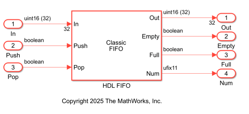
The HDL FIFO block uses these parameter settings:
Register size:
1024– Specifies the FIFO depthMode:
Classic– Implements standard push and pop semanticsData input dimensions:
32– Specifies the number of parallel input elements stored in the FIFOPush onto full register:
Warning– Issues a warning when the FIFO is fullPop empty register:
Warning– Issues a warning when the FIFO is emptyShow empty/full indicators: Enabled – Displays status signals for control logic
Show number of register entries: Enabled – Outputs the FIFO occupancy count
These settings configure a classic FIFO with 1024 entries and a 32-element input vector.
Specify Synthesis Attributes
To implement the HDL FIFO memory using UltraRAM, you must set the ram_style synthesis attribute to ultra. HDL Coder propagates this attribute to the internal Simple Dual Port RAM System blocks that implement the FIFO storage.
To specify the synthesis attribute:
Right-click the HDL FIFO block. To add the HDL Coder app options to the context menu, point to Select Apps and click HDL Coder.
In the HDL Coder section of the context menu, click HDL Block Properties.
Next to the SynthesisAttributes, click Edit.
In the SynthesisAttributes dialog box, set:
Attribute Name to
ram_styleAttribute Value to
ultra
Click OK.
For more information about specifying synthesis attributes, see SynthesisAttributes.
Generate HDL Code, Perform Synthesis, and View Resource Report
To generate HDL code and synthesize it for your the FPGA, use the HDL Workflow Advisor. This example uses Xilinx® Vivado®.
Before you begin, use the hdlsetuptoolpath function to specify the path to the installed Xilinx Vivado executable.
Follow these steps to generate HDL code, perform synthesis, and view the resource report by using HDL Workflow Advisor:
1. Open the HDL Workflow Advisor. In the HDL Code tab, click Workflow Advisor.
2. In HDL Workflow Advisor, in the left pane, Select 1. Set Target > 1.1 Set Target Device and Synthesis Tool, set:
Target workflow to
Generic ASIC/FPGASynthesis tool to
Xilinx VivadoFamily to
Virtex UltraScale+Device to
xcu200-fsgd2104-2-e
3. Select 1.2 Set Target Frequency and set Target Frequency (MHz) to 200.
4. Select 2.1. Check Model Settings and configure the code generation settings as required.
5. To generate HDL code, right-click the 3.1. Set HDL Options task, and select Run to Selected Task.
6.Navigate to 4. FPGA Synthesis and Analysis > 4.2 Perform Synthesis and P/R > 4.2.2. Run Implementation. Clear Skip This Task.
7. Right-click 4.2.2 Run Implementation and select Run to Selected Task.
After synthesis and implementation, view the Resource summary section in the Result pane. This table shows the number of inferred URAM blocks. In this example, the synthesis tool uses 32 UltraRAMs blocks to implement the HDL FIFO.
Resource | Usage | Available | Utilization (%) |
|---|---|---|---|
LUTs | 289 | 1182240 | 0.02 |
CLB Registers | 544 | 2364480 | 0.02 |
DSPs | 0 | 6840 | 0 |
Block RAM Tile | 0 | 2160 | 0 |
UltraRAM | 32 | 960 | 3.33 |
Inspect Generated HDL Code
This generated HDL code shows the implementation of HDL FIFO block. In this code, the input signal is a 32-element vector, and the Num output uses 11 bits, which indicates that the HDL FIFO depth is 1024 entries. The HDL FIFO instantiates SimpleDualPortRAM_generic component. To store the 32-element input vector efficiently, the HDL FIFO uses 32 Simple Dual Port RAMs.
LIBRARY IEEE;
USE IEEE.std_logic_1164.ALL;
USE IEEE.numeric_std.ALL;
USE work.DUT_pkg.ALL;
ENTITY HDL_FIFO IS
PORT( clk        : IN std_logic;
      reset      : IN std_logic;
      enb        : IN std_logic;
      In_rsvd    : IN vector_of_std_logic_vector16(0 TO 31);
      Push       : IN std_logic;
      Pop        : IN std_logic;
      Out_rsvd   : OUT vector_of_std_logic_vector16(0 TO 31);
      Empty      : OUT std_logic; Full : OUT std_logic;
      Num        : OUT std_logic_vector(10 DOWNTO 0) );
END HDL_FIFO;
ARCHITECTURE rtl OF HDL_FIFO IS
COMPONENT SimpleDualPortRAM_generic
GENERIC( AddrWidth : integer;
         DataWidth : integer
);
PORT( clk      : IN std_logic;
      enb      : IN std_logic;
      wr_din   : IN std_logic_vector(DataWidth - 1 DOWNTO 0);
      wr_addr  : IN std_logic_vector(AddrWidth - 1 DOWNTO 0);
      wr_en    : IN std_logic;
      rd_addr  : IN std_logic_vector(AddrWidth - 1 DOWNTO 0);
      dout     : OUT std_logic_vector(DataWidth - 1 DOWNTO 0) );
END COMPONENT;
...
This code shows how the SimpleDualPortRAM_generic component implements the Simple Dual Port RAM System block. This HDL code includes the ram_style synthesis attribute, which directs the synthesis tool to infer UltraRAM.
ENTITY SimpleDualPortRAM_generic IS
GENERIC( AddrWidth   : integer := 1;
          DataWidth  : integer := 1
        );
PORT( clk            : IN std_logic;
      enb            : IN std_logic;
      wr_din         : IN std_logic_vector(DataWidth - 1 DOWNTO 0);
      wr_addr        : IN std_logic_vector(AddrWidth - 1 DOWNTO 0);
      wr_en          : IN std_logic;
      rd_addr        : IN std_logic_vector(AddrWidth - 1 DOWNTO 0);
      dout           : OUT std_logic_vector(DataWidth - 1 DOWNTO 0)
      );
END SimpleDualPortRAM_generic;
ARCHITECTURE rtl OF SimpleDualPortRAM_generic IS
 TYPE ram_type IS ARRAY (2**AddrWidth - 1 DOWNTO 0) of std_logic_vector(DataWidth - 1 DOWNTO 0);
 SIGNAL ram              : ram_type := (OTHERS => (OTHERS => '0'));
 SIGNAL data_int         : std_logic_vector(DataWidth - 1 DOWNTO 0) := (OTHERS => '0');
 SIGNAL wr_addr_unsigned : unsigned(AddrWidth - 1 DOWNTO 0);
 SIGNAL rd_addr_unsigned : unsigned(AddrWidth - 1 DOWNTO 0);
 ATTRIBUTE ram_style : string;
 ATTRIBUTE ram_style OF ram : SIGNAL IS "ultra";
BEGIN
...
The ram_style attribute directs the synthesis tool to map the RAM blocks to UltraRAM resources on the FPGA.
You can also try this example on other FPGA devices that have dedicated UltraRAM resources or use different synthesis tools. For more information about other synthesis attributes supported by various synthesis tools, see Synthesis Attributes in HDL Code Generation.