Validate HDL Design Using Cosimulation with Synopsys VCS
This example shows how to validate an HDL design using cosimulation between Simulink® and an HDL simulator. In this example, you use a Synopsys® VCS® HDL simulator. Cosimulation with Synopsys VCS enables you to use the Simulink model as a testbench while running the HDL design using the VCS simulator. This example uses the Cosimulation Wizard, which uses Verilog® files as its input. The Cosimulation Wizard generates a Simulink block that represents the HDL design in the Simulink model, a MATLAB® script that compiles the HDL design, and a MATLAB script that launches the HDL simulator for cosimulation.
This example uses a pulse detector written in Verilog. A pulse detector is a commonly used technique in radar and wireless communication. The pulse detector algorithm uses a matched filter, which maximizes the signal-to-noise ratio (SNR) and provides the correlation output between the noisy received signal and the matched filter. It then identifies the peak, which indicates the presence of the waveform. To validate the functionality of the pulse detector, this example uses a Simulink testbench. This testbench generates the input to the pulse detector and compares the detected peaks from Simulink and HDL peak detectors.
Requirements
In addition to HDL Verifier™ and Simulink, this example requires the VCS simulator from Synopsys.
Setup
Set up the simulator environment path in MATLAB. Set the environment variable
VCS_HOMEto the path where the VCS is installed.Run
PulseDetectionInputStimulusGenerator.mto load variables into the workspace.This script generates a complex signal containing a randomly phased pulse embedded within a noisy transmission signal. Run this command at the MATLAB command prompt.
PulseDetectionInputStimulusGenerator
3. Open the Simulink testbench model pulse_detector_cosim_tb.slx. Open subsystem block HDL_Pulse_Detector by double-clicking it.
Generate Cosimulation Block Using Cosimulation Wizard
Launch and Configure Cosimulation Wizard
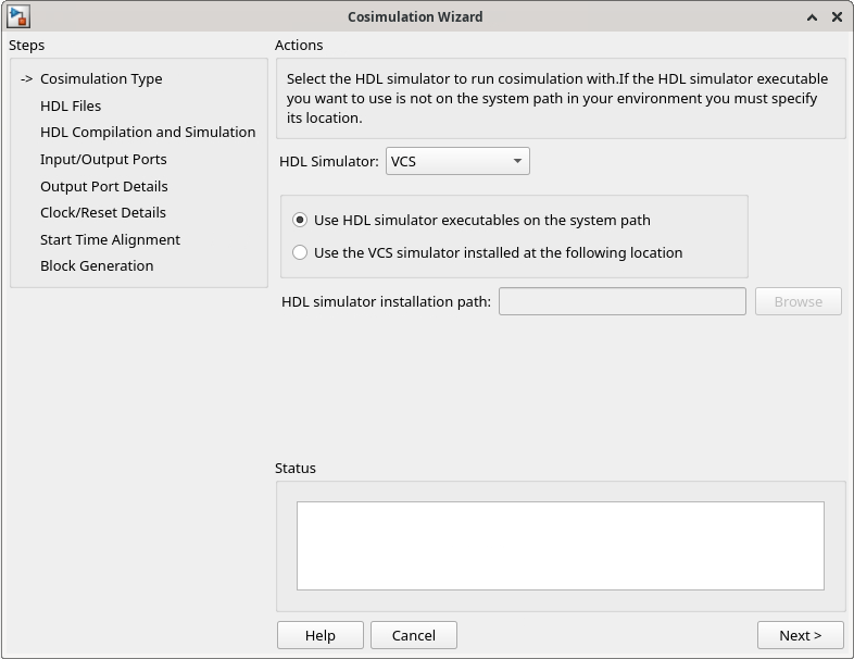
To start the Cosimulation Wizard from the model, select the Apps tab in the Simulink toolstrip and click HDL Verifier. This action adds the HDL Verifier tab to the Simulink toolstrip. Then, in the Mode section, select HDL Cosimulation. Click Import HDL Files in the Generate Cosim Block section.

Change the HDL Simulator option to
VCS.Select Use HDL simulator executables on the system path if the HDL simulator executables appear on your system path. If these executables do not appear on the path, select Use the VCS simulator installed at the following location, and then click Browse to specify the location of these executable files.
Click Next.
Select HDL Files
In the HDL Files pane, specify the files to use for creating the block.
Click Add and select the HDL files provided with the example.
Select
Pulse_Detectoras the Top-Level file.
Click Next.

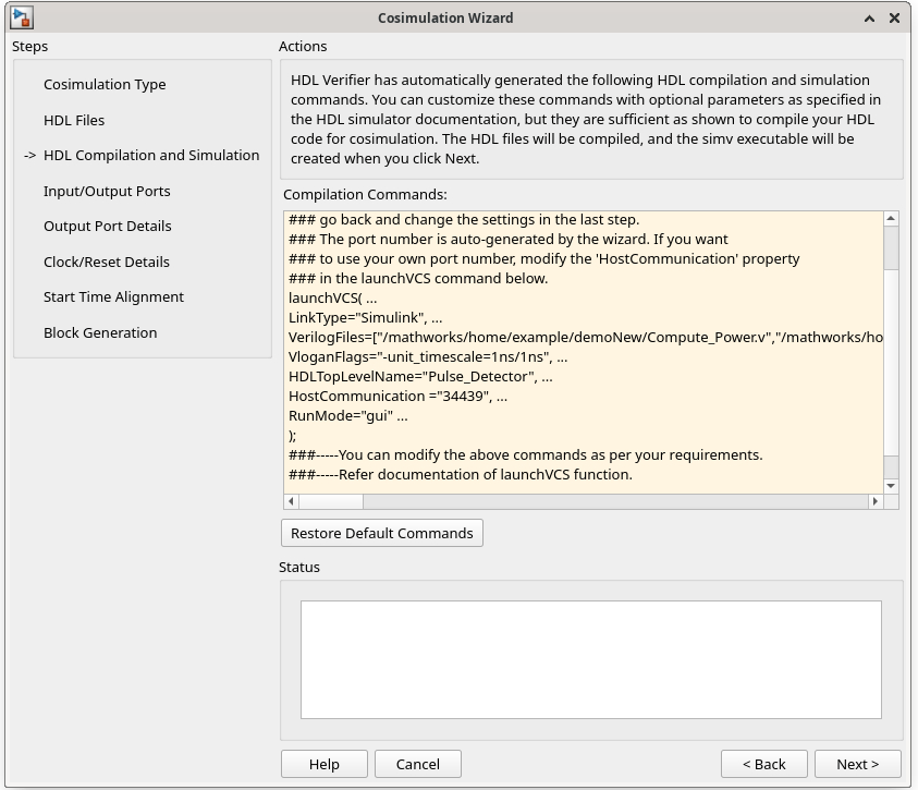
In the HDL Compilation and Simulation pane, the Cosimulation Wizard lists the default commands in the Compilation Commands window. You do not need to change these commands for this tutorial.
Click Next.
Configure Block
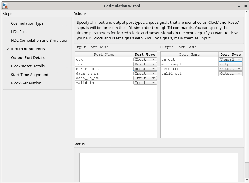
In the Input/Output Ports pane, specify all input and output port types.
Under the Input Port List, set the port type of the clk_enable port as
Reset.Under Output Port List, set the port type of the ce_out port as
Unused.
Click Next.
In the Output Port Details pane, specify all the output data types.
Set Data Type as
Fixedpointfor all four output ports.Set Sign as
Unsignedfor the detected and valid_out ports.
Click Next.

In the Clock/Reset Details pane, set clock and reset parameters. Set Initial Value for clk_enable as 0 and Duration as 1.
Click Next.

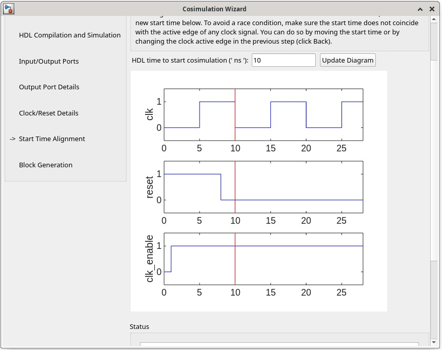
In the Start Time Alignment pane, the Cosimulation Wizard shows the HDL time to start cosimulation with a red line. The start time is also the time at which the Simulink gets the first input sample from the HDL simulator. You do not need to make any changes to the start time.
Click Next.
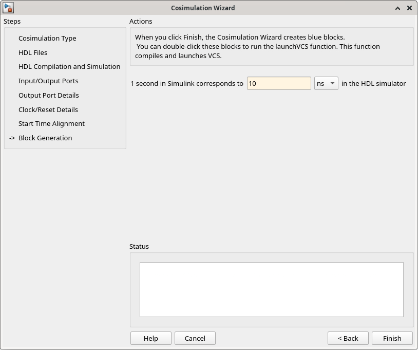
In the Block Generation pane, set the timescale by setting the 1 second in Simulink corresponds to 10 ns in the HDL simulator parameter.
Click Finish to complete the Cosimulation Wizard session.
Create Testbench to Verify HDL Design
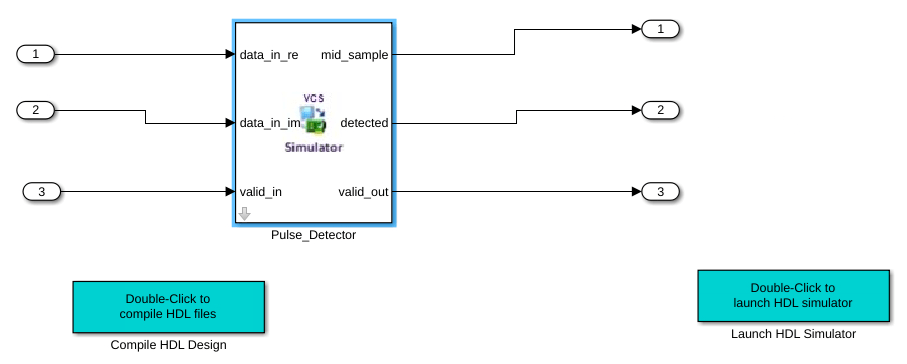
After you click Finish in the Cosimulation Wizard, the following blocks are created in the pulse_detector_cosim_tb/HDL_Pulse_Detector Simulink model.
An HDL Cosimulation block (
Pulse_Detector)A block to recompile the HDL design (contains a link to a script that is launched by double-clicking the block)
A block to launch the HDL simulator (contains a link to a script that is launched by double-clicking the block)
In the pulse_detector_cosim_tb/HDL_Pulse_Detector Simulink model, replace the existing subsystem block with the generated HDL Cosimulation block Pulse_Detector. Connect the Pulse_Detector block to the input and output ports in the testbench model. Your model now looks similar to that in this figure.
Run Cosimulation
Compile the HDL design by double-clicking the block labeled
Compile HDL Design.Start the HDL simulator by double-clicking the block labeled
Launch HDL Simulator.In the VCS terminal, type the
runcommand.Run the Simulink testbench.
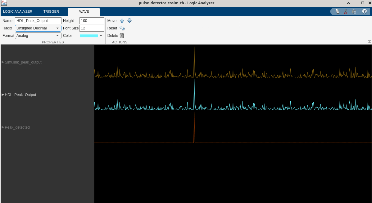
Open Logic Analyzer, from the Simulink toolstrip.
Observe that the Simulink peak output coincides with the peak of the pulse detector implemented using HDL.
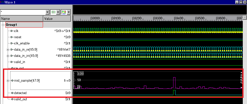
You can also observe your output in the VCS simulator. Open VCS waveform viewer and observe the mid_sample and detected signals. For better visualization, make sure that you have selected Style_scheme as analog for the mid_sample signal.
Conclusion
In this example, you validate a pulse detector HDL design by cosimulation between Simulink and Synopsys VCS HDL simulator. You created a Simulink testbench that provides signals as input to your HDL design. You validate the output by comparing the output of the Simulink model and the HDL design in Logic Analyzer. By generating stimulus from the Simulink testbench, you reduce the time required to create a full-featured HDL testbench. You also leverage the various capabilities of MATLAB and Simulink to observe the results.