Poppet Valve (TL)
Poppet flow control valve in a thermal liquid network

Libraries:
Simscape /
Fluids /
Thermal Liquid /
Valves & Orifices /
Flow Control Valves
Description
The Poppet Valve (TL) block represents the flow control within a thermal liquid network. You can specify the seat geometry as either sharp-edged or conical. Set the poppet displacement with the physical signal at port S.
Mass Balance
The mass conservation equation in the valve is
where:
is the mass flow rate into the valve through port A.
is the mass flow rate into the valve through port B.
Momentum Balance
The pressure differential over the valve is:
where:
pA is the pressure at port A.
pB is the pressure at port B.
is the mass flow rate.
ρAvg is the average liquid density.
Cd is the value of the Discharge coefficient parameter.
is the critical mass flow rate:
where:
Recr is the value of the Critical Reynolds number parameter.
μAvg is the average fluid dynamic viscosity.
S is the value of the Cross-sectional area at port A and B parameter.
PRLoss is the pressure ratio:
Energy Balance
The energy conservation equation in the valve is
where:
ϕA is the energy flow rate into the valve through port A.
ϕB is the energy flow rate into the valve through port B.
Opening Area With a Sharp-Edged Seat
When you set Valve seat specification to
Sharp-edged, the block calculates the valve opening
area using
where:
ro is the valve orifice radius.
rp is the valve poppet radius.
dOB(h) is the distance between the center of the poppet and the edge of the orifice. This distance is a function of the valve lift,h.
Aleak is the leakage area.
The maximum displacement, hmax, is
The figure shows a schematic of a hard-edged seat.
Opening Area With a Conical Seat
When you set Valve seat specification to
Conical, the block calculates the valve opening area
using a geometric relationship, such that
The maximum displacement, hmax, is:
where θ is the Cone angle. The figure shows a schematic of a conical seat.
Numerically Smoothed Displacement
The block calculates the poppet displacement, h, such that
where:
S is the physical signal input.
Smin is the Poppet position when in the seat parameter.
hMax is the maximum displacement.
If the Smoothing factor parameter is nonzero, the block smoothly
saturates the poppet displacement between 0 and
hMax.
For more information, see Numerical Smoothing.
Examples
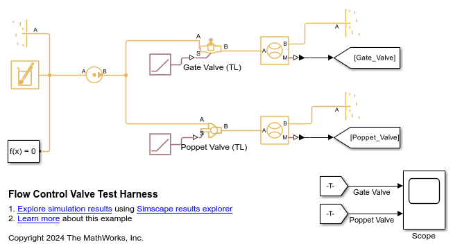
This example uses test harnesses to compare the Gate Valve (TL) and Poppet Valve (TL) blocks. A test harness is a minimum viable model that you can use to parameterize blocks or isolate dynamics.
Model
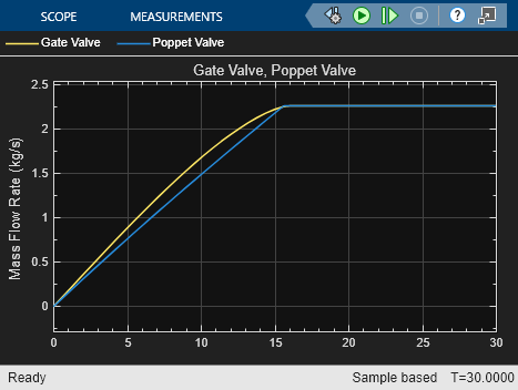
Simulation Results from Scopes
This figure shows the mass flow rate through each of the valves. Both valves start closed and slowly open before reaching their maximum area. At the maximum area, the mass flow rate also reaches its maximum and cannot increase further. Both curves have a different profile while opening because each valve has a different area profile that depends on the valve geometry.
Ports
Conserving
Input
Parameters
Extended Capabilities
Version History
Introduced in R2016a