Reduced Order Modeling of Subsystems in Engine Model
This example shows how to create a reduced order model (ROM) of subsystems in a Simulink® engine model using a nonlinear ARX model. You can then replace the subsystems with the ROM to obtain similar simulation results in a shorter period of time.
In this example, you create a ROM of the Induction and Combustion subsystems in the Simulink model enginespeed. You use the Reduced Order Modeler app to:
Specify ROM inputs and outputs.
Design experiments.
Generate input and output data from the Simulink model.
Train an AI-based surrogate model from the input and output data using preconfigured training templates.
Implement the trained model in Simulink.
This example describes the complete workflow to create a ROM. To use a ROM that was pretrained by following the steps in this example, begin at the Use Trained ROM in Simulink step.
For more information, see Reduced Order Modeling (Simulink).
Open Model and Reduced Order Modeler App
Open the Simulink model enginespeed.
sys = 'enginespeed';
open_system(sys)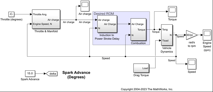
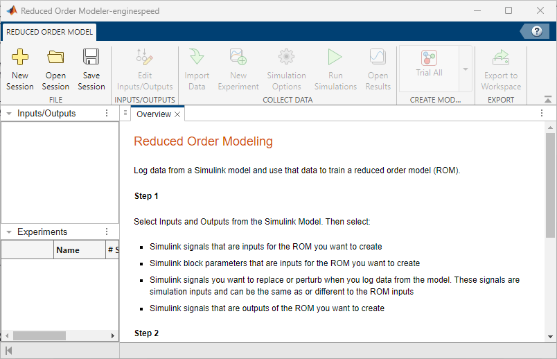
Open the Reduced Order Modeler app.
reducedOrderModeler(sys)
Select ROM Inputs and Outputs
Select the Simulink signals and block parameters that are inputs and the Simulink signals that are outputs of the ROM you are creating. Also select the Simulink signals that are simulation inputs. You replace or perturb the simulation inputs when you simulate the enginespeed model to generate data for training the ROM.
In the app, on the Reduced Order Model tab, click New Session. The Select ROM I/Os dialog box opens.
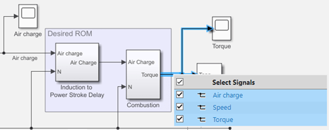
In the Select ROM I/Os dialog box, click Select Signals. The Simulink model appears in a mode where you can interact with it and select signals.
To select a signal, click the signal in the model and then select it in the list that appears. Select the input signals
Air chargeandSpeedand the output signalTorquefor the ROM.
In the Select ROM I/Os dialog box, change the I/O Type of the
Torquesignal toROM Output. Do not change the I/O Type ofAir chargeorSpeedfrom the default type,ROM & Simulation Input. SpecifyingAir chargeandSpeedas ROM and simulation inputs allows you to collect data from simulations using differentAir chargeandSpeedsignal values.Click Select Parameters. The Simulink model appears in a mode where you can interact with it and select parameters.
To select a parameter, click the corresponding block in the model and select the parameter in the list that appears. Select the parameter
Spark Advance.Keep the I/O Type of
Spark Advanceas the default type,ROM & Simulation Input. Specifying the parameter as both ROM and simulation input allows you to collect data for different parameter values representing different conditions.
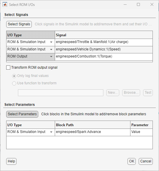
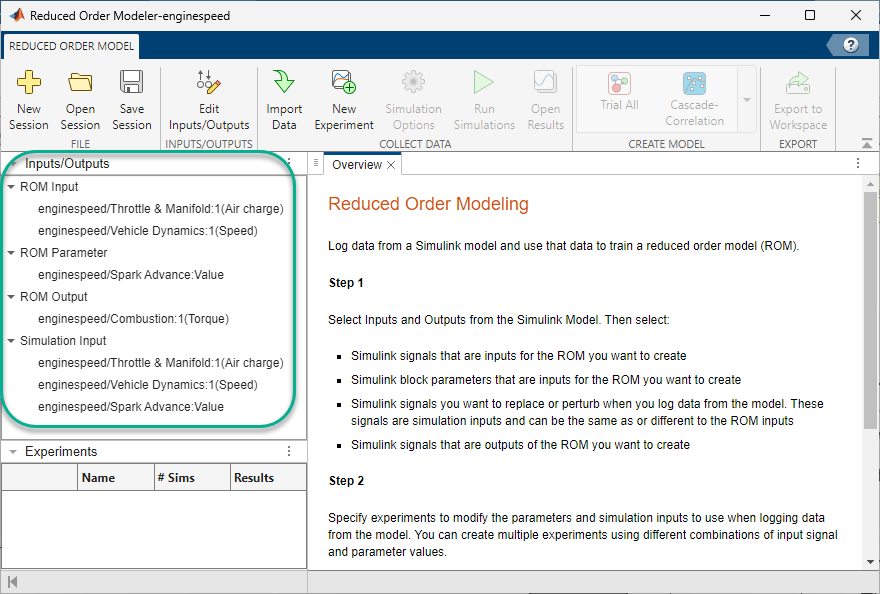
Click OK. The selected inputs, parameters, and outputs appear in the Inputs/Outputs pane in the Reduced Order Modeler app.
Configure Experiment
Configure an experiment to generate input and output data from the enginespeed model for training the ROM. To customize the simulation inputs in this experiment, follow these steps:
On the Reduced Order Model tab, click New Experiment. The Experiment and Experiment Signals tabs open.
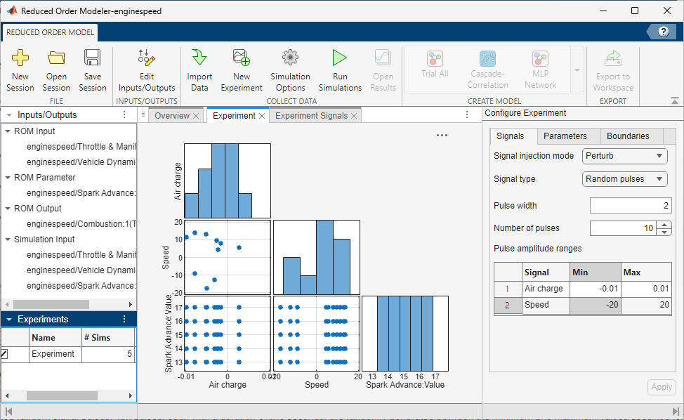
Your ROM needs to work within an operating range around the signal values obtained from a baseline simulation of the engine model. So, add perturbation to the signal values. In the Configure Experiment pane, on the Signals tab, set the Signal injection mode as
Perturb.Keep Signal Type, Pulse width, and Number of pulses as their default values of
Random pulses,2, and10, respectively.Random pulsesspecifies that the app selects signal perturbations at random within the signal range.Specify the minimum and maximum amount of perturbations of the signal inputs in the Min and Max columns:
Signal | Min | Max |
|---|---|---|
|
|
|
|
|
|
On the Parameters tab, in the Values cell of
Spark Advance, set the range to 13 to 17 degrees by typing13:17. The experiment will sweep through each of the five integer values from 13 to 17. It will run five simulations, with each simulation using a different integer value ofSpark Advance. Click Apply.
For more information on the options available for configuring experiments, see Configure Options in Reduced Order Modeler (Simulink).
On the Experiment tab, a scatter plot shows the relationships between input signals and parameter values.
The Experiment Signals tab shows the random signal pulses that the app generates to be used when running the experiment. The software randomly generates ten two-second pulses within the range of values specified for each signal. Because you specified Signal injection mode as Perturb, these pulses are the signal perturbations, not the actual values of the signals.
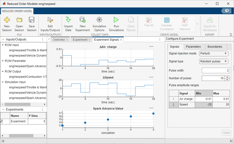
In the Experiments pane, the # Sims value is 5, where one simulation corresponds to one parameter value. You can see the Spark Advance parameter value in each simulation in the bottommost plot on the Experiment Signals tab.
Run Experiment
Log the input, parameter, and output data for training the ROM by running the Simulink model with the experiment you configured. This experiment definition produces five simulation runs, one for each parameter value.
On the Reduced Order Model tab, click Run Simulations.
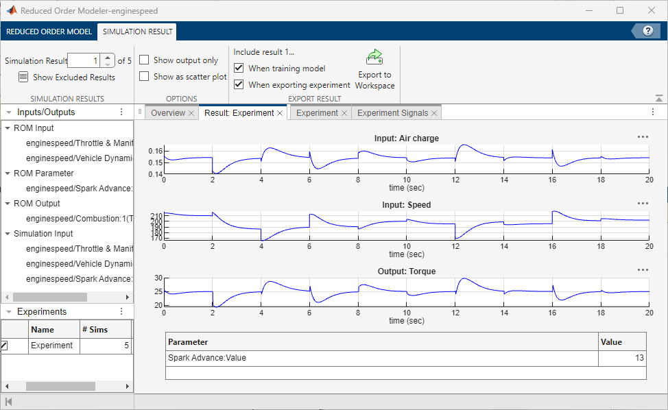
View the simulation results. To choose a simulation result to view, on the Simulation Result tab, select a simulation number in the Simulation Result box. The Result: Experiment tab shows plots of the input and output signal values from the selected simulation. A table below the plots shows the Spark Advance parameter value that the simulation used.
Create ROM Using Nonlinear ARX Model
Train a ROM using the simulation results. First, open Experiment Manager:
On the Reduced Order Model tab, in the Create Model gallery, select Nonlinear ARX as the model type. The Export Results dialog box opens.
In the Export Results dialog box, select all experiments and signals and click OK.
In the Create Experiment dialog box, select New Project, click OK, and save the experiment project. The Experiment Manager app opens.
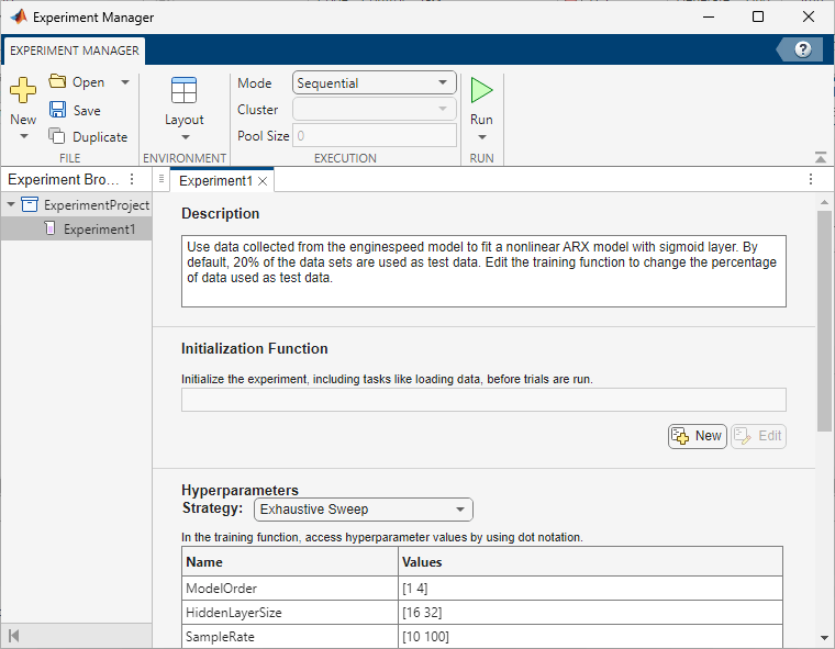
Experiment Manager creates an experiment to train a nonlinear ARX model using the simulation results. To view experiment information such as the high-fidelity system, ROM model type, and test data percentage in Experiment Manager, view the Description text box on the Experiment1 tab.
Set the Hyperparameters Strategy to Exhaustive Sweep. Experiment Manager sweeps over different hyperparameters to train different models, then determines which models work best. For training, use the default hyperparameters.
You can also edit the function used to train the nonlinear ARX model. To open the training function, in the Training Function section, click Edit. For this example, use the default training function.
By default, Experiment Manager runs one trial of the experiment at a time. If you have Parallel Computing Toolbox™ software, you can run multiple trials at the same time or offload your experiment as a batch job in a cluster.
To train the models, on the Experiment Manager tab, click Run.
On the Experiment1 | Result1 tab, each row in the results table represents a trained model. The row for each model displays each of its hyperparameter values, as well as model performance information and metrics:
TrainingMSE is the mean squared error calculated on the training data set. It is the average squared difference between the output obtained by simulating the original model and the output predicted by the trained model, using the training data values. Because the training data values were used to train the model, TrainingMSE shows how well the model fits the data used to train it.
TestMSE is the mean squared error calculated on the test data set. It is the average squared difference between the output obtained by simulating the original model and the output predicted by the trained model, using the test data values. Because the test data values were not used to train the model, TestMSE shows how well the model performs on new data.
TrainingLoss is the measure of inaccuracy of the model predictions calculated on the training data set. It shows how the model progresses by learning from the training data.
Sort the trained models by TrainingLoss in ascending order by clicking the arrow on the right of the TrainingLoss column header and selecting Sort in Ascending Order in the list that appears.
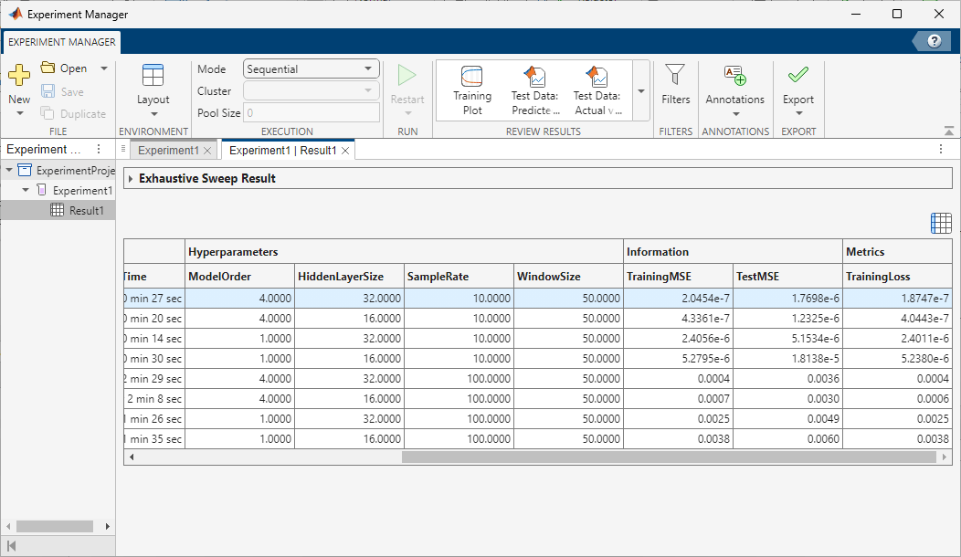
Of the models you trained, export the model with low TestMSE, reasonable TrainingMSE, and low TrainingLoss. To export a model as a workspace variable, first, select its row in the results table. On the Experiment Manager tab, in the Export menu, click Training Output. Name the workspace variable trainingOutput and click OK. Because the experiments that generate the training data use random pulse sequences for the input signal perturbations, model performance might vary.
You can also export a model directly into Simulink. For more information, see Export Models from Experiment Manager into Simulink (Simulink).
For more information on hyperparameters and metrics, see Configure Options in Reduced Order Modeler (Simulink).
Use Trained ROM in Simulink
Note: You can begin at this step by loading a previously trained nonlinear ARX model, trainedModel.mat. This model was trained using data generated by experiments configured as shown in this example. To load the model, at the command line, enter:
load('trainedModel.mat')The trainingOutput variable stores the trained nonlinear ARX model and the associated data.
trainingOutput.NonlinearModel
ans =

Nonlinear ARX model with 1 output and 3 inputs
  Inputs: Air charge, Speed, Spark Advance:Value
  Outputs: Torque

Regressors:
  Linear regressors in variables Torque, Air charge, Speed, Spark Advance:Value
  List of all regressors

Output function: Sigmoid network with 15 units
Name: NLARX Model
Sample time: 0.1 seconds

Status:
Estimated using NLARX on time domain data "zTrain".
Fit to estimation data: [99.97 99.97 99.98 99.97]% (simulation focus)
FPE: 2.192e-07, MSE: [1.736e-07 2.434e-07 1.359e-07 1.656e-07]

Model Properties
Run the original Simulink model. Record the steady-state input and output signal levels by looking at the Scope blocks of Air charge, Speed, and Torque signal levels. You will use these values to set initial conditions for the trained ROM.
sim("enginespeed")To replace the Induction and Combustion subsystems in the enginespeed Simulink model with the ROM:
Delete the Induction and Combustion subsystems in the model.
Add a From block to the model and specify the Goto tag block parameter as
delta. The From block now passes theSpark Advanceparameter as the output.Add a Vector Concatenate block to the model and specify the Number of inputs block parameter as
3.Connect the
Air chargesignal,Speedsignal, and the From block as inputs to the Vector Concatenate block.Add a Nonlinear ARX Model block to the model. To set the initial conditions of the Nonlinear ARX Model block such that it uses the trained ROM and the input and output signal levels match those of the original subsystems, set the block parameters:
Parameter | Value |
|---|---|
Model |
|
Initial conditions |
|
Input levels (scalar or vector of length equal to number of model inputs) |
|
Output level (scalar) |
|
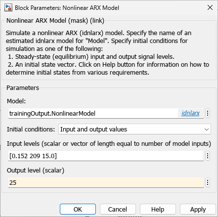
Click Apply and then click OK.
Connect the output of the Vector Concatenate block to the input of the Nonlinear ARX Model block. Connect the output of the Nonlinear ARX Model block to the
Torquesignal.
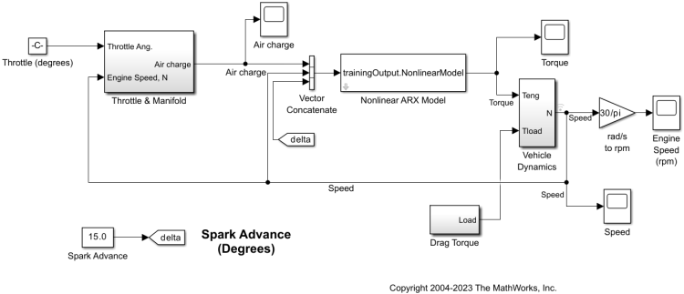
Run the model. The results are similar to those of the original model. For example, the Engine Speed scope displays the same signal level as the original model.
See Also
Reduced Order Modeler (Simulink) | Experiment Manager
Topics
- Reduced Order Modeling (Simulink)
- Configure Options in Reduced Order Modeler (Simulink)
- Export Models from Experiment Manager into Simulink (Simulink)