Automatic Radar Waveform Generation and SDR Receiver Calibration Using Signal Generator
This example shows you how to systematically calibrate a radar SDR receiver using a customized MATLAB application that automates waveform generation, data capture, correction processing, and result analysis across multiple radar waveforms. The workflow coordinates three hardware components: an external signal generator (connected via VISA interface) that transmits RF waveforms, an ADALM-PLUTO SDR acting as the Device Under Test (DUT), and an Arduino-controlled servo motor that provides automated positioning for systematic testing.
This calibration workflow provides a systematic approach to characterizing the radar receiver performance by automating waveform testing, correction application, and result analysis. The workflow demonstrated in this example using an ADALM-PLUTO SDR is extensible to phased array systems. By automating the generation, transmission, and analysis of various radar waveforms, this workflow enables:
Automated receiver characterization for multiple radar waveforms
Correction of common receiver impairments (DC offset, I/Q imbalance, frequency offset)
Range-dependent calibration using motorized positioning systems
Systematic data collection for post-processing and analysis
The workflow is particularly useful for:
Validating receiver performance across different radar waveform types
Characterizing antenna element responses in phased arrays
System Architecture
In this example, the MATLAB‑based host computer serves as the Test Sequence Management and Analysis Computer, coordinating all test equipment, collecting data, applying real‑time signal corrections, managing test sequences, and storing the results.
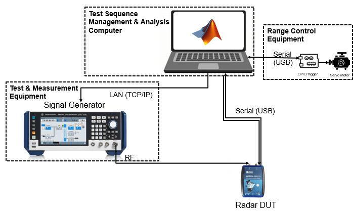
The test sequencer manages the calibration workflow through integrated control of three components:
Signal Generation (RF Signal Generator)
The RF signal generator generates and transmits various radar waveforms using the
rfsiggen(Instrument Control Toolbox) function.The instrument must support TCP/IP interface and use AgRfSigGen, RsRfSigGen, AgRfSigGen_SCPI, or RsRfSigGen_SCPI driver. For more information, see Quick-Control RF Signal Generator Requirements (Instrument Control Toolbox).
This example uses SMBV100B Rohde and Schwarz signal generator along with Instrument Control Toolbox™ Support Package for R&S® VISA interface.
Device Under Test (ADALM-PLUTO SDR)
The DUT acts as the radar receiver under calibration that captures the RF signal and converts it into I/Q samples for real-time processing and analysis.
This example uses ADALM-PLUTO SDR along with Communications Toolbox Support Package for Analog Device ADALM PLUTO Radio, with configurable receive parameters.
Range Control System (Arduino Board and Servo Motor)
The Range Control System provides automated positioning of the receiver/antenna to systematically test performance across different angular positions — individual antenna elements in phased arrays or different orientations for single-element receivers like the ADALM-PLUTO.
This example uses an Arduino Uno board with a servo motor that provides the physical positioning mechanism to align the calibration probe with the receiver during calibration measurements. The connection and control is done using MATLAB Support Package for Arduino Hardware.
Calibration Workflow Process
The automated calibration workflow executes the following coordinated sequence for each test point (radar waveform):
Position Control: The MATLAB host computer (sequencer) commands the Arduino-controlled servo motor to move to the receiver/antenna to a specified angular position, enabling systematic testing across different orientations or simulating different array element positions.
Signal Generator Configuration: The sequencer configures the vector signal generator (SMBV100B) via the VISA interface using the
rfsiggenAPI, setting up the required waveform parameters including sample rate, center frequency, and modulation characteristics.Receiver Configuration: The ADALM-PLUTO SDR is configured with appropriate receive parameters matching the transmitted waveform, including center frequency, sample rate, and gain settings.
Signal Transmission and Capture: The sequencer triggers the signal generator to transmit the RF waveform while simultaneously commanding the ADALM-PLUTO to capture the received signal for the specified duration.
Data Collection and Processing: The captured I/Q data is retrieved from the ADALM-PLUTO, and real-time corrections are applied including DC offset removal, I/Q imbalance compensation, and frequency offset correction.
Results Storage: Processed data along with complete metadata (waveform parameters, position information, correction values) is stored for post-processing analysis.
This sequence repeats automatically for all configured positions and waveform types in the test plan, building a comprehensive calibration dataset. The automation ensures consistent test execution while eliminating manual intervention errors.
Hardware Requirements and Connections
To implement the automated calibration workflow, you must establish proper connections between the host computer and all test equipment. The setup requires the following cables and connections.
Required Hardware
SMBV100B signal generator (or compatible RF signal generator)
ADALM-PLUTO SDR
Arduino Uno board
Servo motor with mounting bracket
Ethernet cable
RF coaxial cable with SMA to N-type connectors
Two USB cables (Type-A to micro-USB, and Type-A to Type-B)
Hardware Connections
Follow these steps to connect the hardware components:
1. Connect Host Computer to Signal Generator
Connect an Ethernet cable from your host computer's network interface to the LAN port on the signal generator. This connection uses TCP/IP protocol via VISA interface.
Configure the signal generator with a known IP address (either static or via DHCP). You will enter this IP address in the application GUI when establishing the connection.
Note: Ensure that the host computer and signal generator are on the same network subnet. You may need to configure firewall settings to allow VISA/SCPI communication.
2. Connect Signal Generator to ADALM-PLUTO SDR
Connect the RF output port of the signal generator to the RX port of the ADALM-PLUTO SDR using an RF coaxial cable.
Note: Ensure that the signal generator output power does not exceed -10 dBm to protect the SDR. Use attenuators if necessary.
3. Connect Host Computer to ADALM-PLUTO SDR
Connect a USB cable (USB Type-A to micro-USB) from the host computer to the ADALM-PLUTO SDR.
4. Connect Host Computer to Arduino Board
Connect a USB cable (USB Type-A to Type-B) from your host computer to the Arduino Uno. Note the assigned COM port for GUI configuration.
5. Connect Servo Motor to Arduino
Connect the servo motor's three-wire connector to the Arduino board:
Signal wire: Arduino digital pin 9
Power wire: Arduino 5V pin
Ground wire: Arduino GND pin
Mount the ADALM-PLUTO SDR or antenna on the servo motor arm for angular positioning.
Note: If the servo requires more current than the Arduino can provide, use an external 5V regulated supply. Ensure the external supply GND is tied to Arduino GND.
Verify Connections
After completing all hardware connections, verify the setup before launching the application:
Power-on the signal generator and verify network connectivity by pinging the IP address from the host computer.
Connect the ADALM-PLUTO SDR and verify the USB connection. The SDR should appear as a network adapter in your system.
Connect the Arduino board and verify that it appears in the COM port list (Windows).
Ensure that the servo motor is properly mounted and can rotate freely without obstruction.
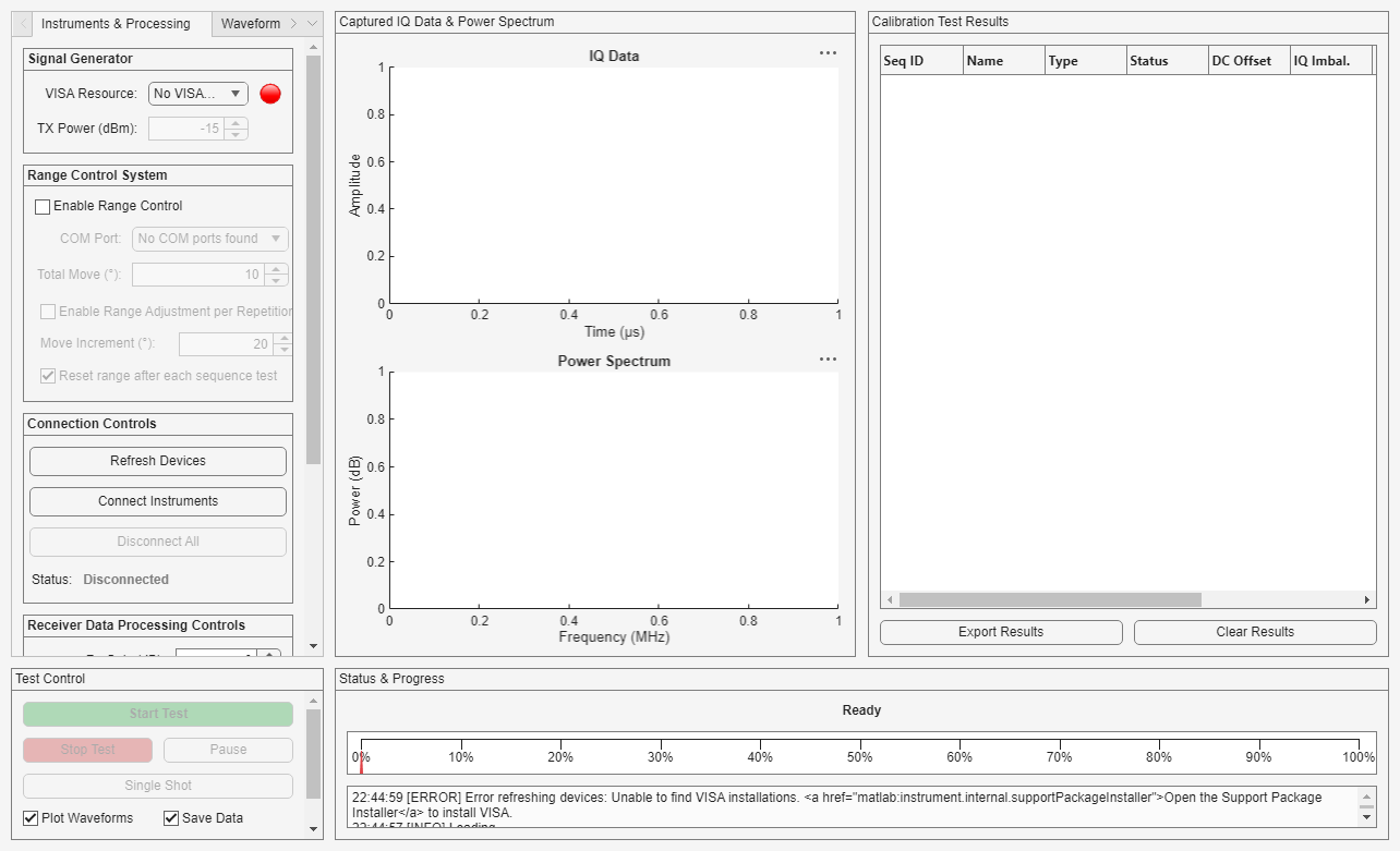
Launch the Application
After you complete the physical connections required for the example and power-on the components, launch the Automatic Waveform Generation application by running this code:
% Launch the app
try
app = RadarWaveformGenerationApp();
catch ME
    errordlg(['Failed to launch application: ' ME.message], 'Launch Error');
    rethrow(ME);
end
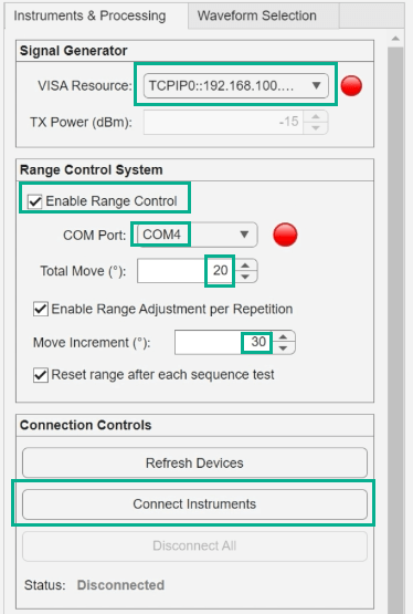
Set Up VISA Resource and Configure Range Control
The VISA Resource dropdown in the Signal Generator pane of the app lets you select the available signal generator that is connected to the host computer, and identified using its resource name depending upon the installed VISA driver. If you face issues identifying the VISA resource in the dropdown, refer to Troubleshooting VISA Interface (Instrument Control Toolbox) and Resolve VISA Connection Errors (Instrument Control Toolbox).
To configure Range Control System, select the Enable Range Control parameter. This option is included because the associated hardware is optional and may be customized differently across workflows. When enabled, you can specify the remaining range control parameters as required for your workflow:
COM Port : The system automatically scans for available COM ports. Select the appropriate COM port connected to your Arduino Uno board.
Total move defines the servo motor angular movement during each waveform transmission.
Selecting the Enable Range Adjustment per Repetition parameter enables automated sequential positioning for antenna array based DUT. Since each repetition typically corresponds to testing a different antenna element, the system automatically increments the servo position between repetitions to align the RF source with each element's physical location. The Move Increment field defines the angular offset (in degrees) to add to Total move after each repetition, useful when antenna elements are physically separated.
Selecting the Reset range after each sequence test parameter returns the positioning system to its initial state after completing the test sequence, preparing for the next test sequence.
Click Connect Instruments to complete the configuration for signal generator and range control system.
If the connection is successful with the specified configurations, the indicator color changes from red to green, and the status displays All Connected.
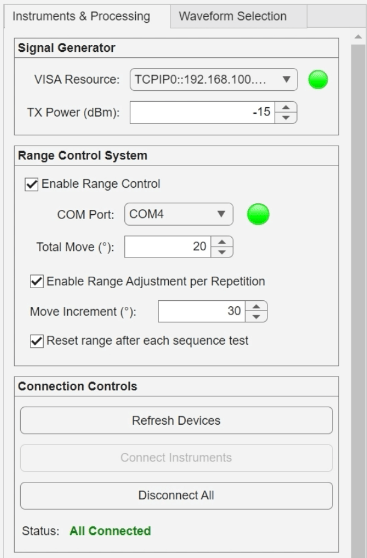
The TX Power parameter in Signal Generator pane can be configured if the connection was successful. The transmit power level defines the exact amount of energy the VISA resource (SMBV100B) injects into the system. The unit is dBm (decibels relative to 1 milliwatt).
Note: You must specify a value that is low enough not to damage the radar receiver (ADLAM-PLUTO).
Note: The example uses arduino and servo objects, available through the MATLAB Support Package for Arduino Hardware. During the Hardware Setup process of this support package, ensure that the Servo library is installed and the Arduino Uno board is properly detected.
Set Up Receiver Gain and Calibration Correction
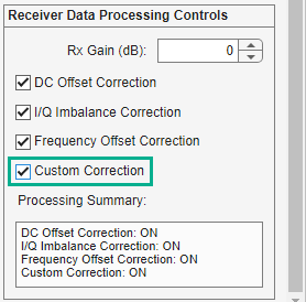
Use the Receiver Data Processing Controls pane in the app to configure the ADALM PLUTO receiver gain parameter and enable real-time signal correction algorithm for calibration measurements.
The system provides four automated correction algorithms that can be independently enabled to compensate for common receiver impairments.
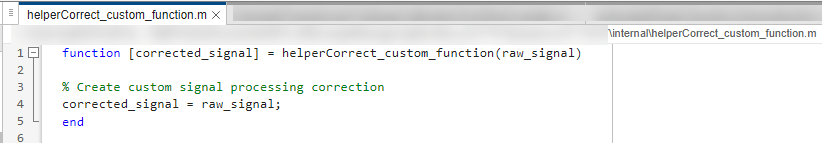
You can implement custom correction using the Custom Correction parameter, which also requires that you add the correction in the helperCorrect_custom_function file available in the internal folder of the example.
Waveform Selection and Configuration and Start Automated Test Sequence
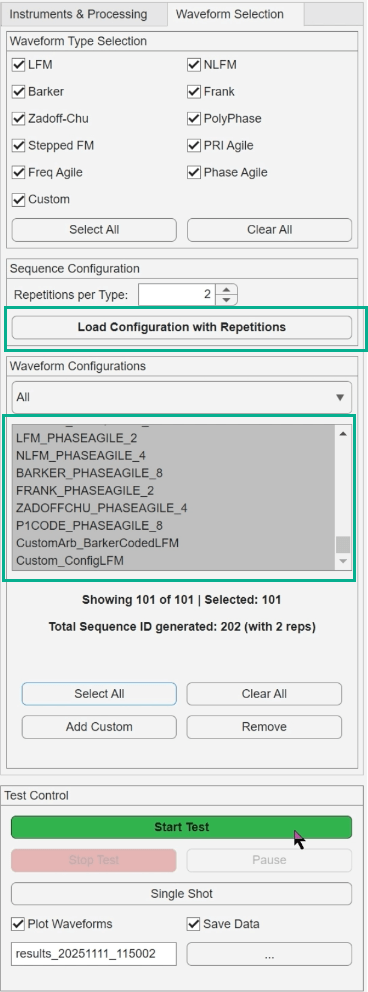
The Waveform Selection tab in the app allows you to:
Select desired waveform types: In the Waveform Type Selection panel, choose from a comprehensive library of radar waveforms—including LFM, NLFM, Barker, Frank, Zadoff-Chu, Polyphase, and Stepped FM—as well as agile waveforms such as PRI-agile, frequency-agile, and phase-agile types. The interface supports pre-configured Phased Array Toolbox pulsed radar waveforms and agile/custom waveform definitions.
Set global repetition count: The Repetitions per Type parameter defines how many times each waveform configuration will be tested. This is useful for an antenna array system, where each repetition typically corresponds to testing a different antenna element.
Load configurations: Click Load Configuration with Repetitions to generate the complete test sequence
Add custom waveform: Add a custom radar waveform configuration to the test sequence list.
Select the required values in Waveform Configurations list that you want to include in the test sequence. Click Select All to test the complete set. Once your selection is made, click Start Test to begin the automated test sequence.
Monitor IQ Data and Power Spectrum and Analyze the Results
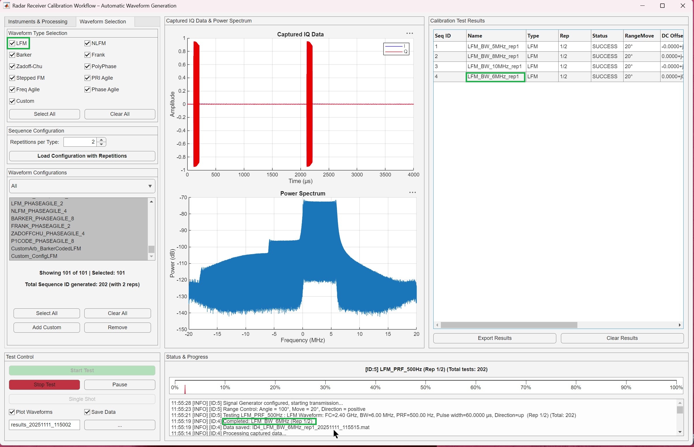
After the tests start, you can:
Monitor real-time progress and status
View live I/Q data and power spectrum plots
Monitor the corrections applied to the waveform
Pause and resume or stop testing as needed
The Calibrated Test Results table shows the results with correction metrics applied for all selected waveform configurations. To export data for post-processing, click Export Results.
Summary
This example demonstrated an automated calibration workflow for phased array radar receivers using the Automated Radar Waveform Generation App. The MATLAB application coordinates a signal generator (via VISA interface), an ADALM-PLUTO SDR , and an Arduino-controlled positioning system to systematically test multiple radar waveforms across different orientations. This integrated approach enables comprehensive receiver characterization with automated IQ data corrections, providing the calibration data essential for optimal receiver performance.