Configure Radar Using a Configuration (.cfg) File for Reading Detections
R2026bTo configure the TI mmWave radar board, you must send a sequence of commands to the board using the serial port. This sequence specifies parameters such as the chirp profile, sampling rate, and desired outputs. The commands must be saved in a configuration (config) file with a .cfg extension and used in the appropriate workflow to configure the radar. For more information on the commands, see the user guide for respective boards.
For all supported boards except IWRL643BOOST and AWR2944EVM, see the Configuration (.cfg) File Format section in MMWAVE SDK User Guide.
For IWRL6432BOOST, refer to Parameter Tuning and Customization Guide for the IWRL6432 Motion/Presence Detection Demo. You can find information about this guide at this link.
For AWR2944EVM, see the Configuration (.cfg) File Format section in MMWAVE MCUPLUS SDK User Guide
Specify Config File for mmWaveRadar and dca1000
For the mmWaveRadar
object that is used to read detections, and the dca1000
object that is used to read IQ data (ADC data) in MATLAB, use the property or name-value
argument ConfigFile to specify the required config file. You need
to specify the filename with full file path and extension.
For instance, if tiradar is the name of the
mmWaveRadar object that you created and you want to configure the
radar using the file C:\Configs\
xwr68xx_2Tx_BestRange_UpdateRate_10.cfg, then specify the config file as
shown below:
tiradar.ConfigFile = "C:\Configs\ xwr68xx_2Tx_BestRange_UpdateRate_10.cfg";
The mmWaveRadar object and dc1000 object set a
few properties of the object based on the parameters in the configuration file.
Note
The outputs returned by the mmWaveRadar object depend on the
configuration (.cfg) file that you use. For information about the supported outputs
in MATLAB, see mmWaveRadar. When streaming heat map data,
use a frame rate of 5 fps or lower. The achievable frame rate depends on the board
and the configured data port baud rate. For more information, see Performance Considerations for Using mmWave Radar Sensors for Reading Object Detections.
Specify Config file for Read Detections Block
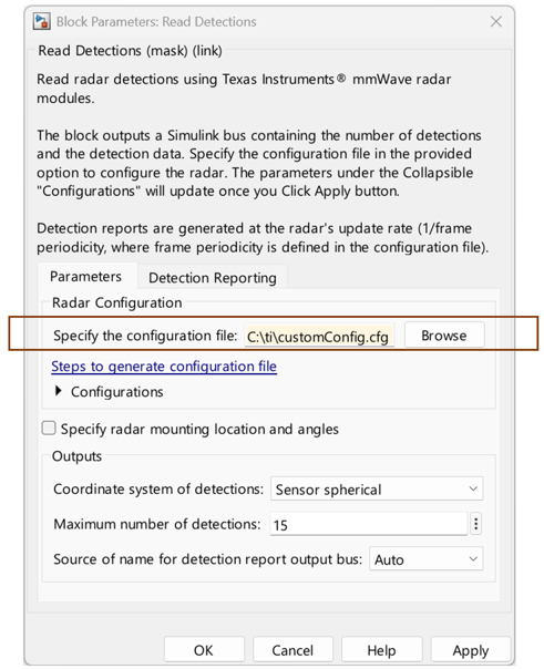
For Read Detections block in Simulink, specify the config file in the option available in the block mask. You need to specify the filename with full file path and extension.
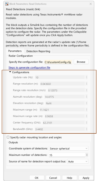
After you click Apply, the parameters under Configurations get updated as per the specified configuration file.
Note
To read detections using the Read Detections block, enable the parameter that outputs detections (point cloud) in the Configuration (.cfg) file.
Sample Config Files
You can use a sample configuration file provided with the support package instead of
generating a configuration file. The sample files are stored in the
configfiles folder in TI Radar Support package install directory.
To navigate to this directory, execute the following commands in MATLAB® command window.
installDir = matlabshared.supportpkg.getSupportPackageRoot
tiradarCfgFileDir = fullfile(installDir,'toolbox','target', 'supportpackages', 'timmwaveradar', 'configfiles');
cd(tiradarCfgFileDir)
If you are using advanced frame configuration, the corresponding sample files can be
found in the subframe folder inside the
configfiles folder.
Once you identify the config file you need to use to configure the TI radar, specify this file name with full file path and extension as mentioned in the previous sections.
Generate Configuration File for All Supported Boards Except IWRL6432BOOST
Instead of using the sample files, you can use your own Configuration (.cfg) file and
specify the full path to the file while defining the ConfigFile
property.
For all the supported boards except the IWRL6432BOOST and AWR2944EVM, use mmWave Demo visualizer 3.6.0 application to generate the configuration file.
Use the Setup Details and Scene Selection sections in the application to specify the required configurations.
Select the appropriate platform for your TI board:
xwr68xx for TI IWR6843ISK or TI AWR6843ISK
xwr68xx_AOP for TI IWR6843AOPEVM or TI AWR6843AOPEVM
xwr16xx for TI AWR1642BOOST or TI IWR1642BOOST
xwr18xx for TI AWR1843BOOST or TI IWR1843BOOST
xwr18xx_AOP for TI AWR1843AOP
xwr64xx for TI IWRL6432BOOST
In the mmWave Demo Visualizer, use the check boxes in Plot Selection section to specify the required outputs:
Select Scatter plot for getting detections (point cloud) outputs.
Select Range Profile and Noise Profile for getting range profile and noise profile outputs respectively.
Select Range Doppler Heat Map and Range Azimuth Heat Map for getting range doppler and range angle responses in outputs respectively.
Once you have specified the required configurations, click Save
Config to PC to generate the corresponding .cfg file.
Generate Configuration (.cfg) File for IWRL6432BOOST
To generate the Configuration (.cfg) file for the IWRL6432BOOST, refer to
Parameter Tuning and Customization Guide for the IWRL6432 Motion/Presence
               Detection Demo
. You can find information about this guide at this link.
Generate Configuration (.cfg) File for AWR2944EVM
If you are using AWR2944EVM, use mmWave Demo visualizer version 4.7.0
to generate the configuration file. Select the platform as AWR294X and select
awr2944. The generated file is also based on your selection for
the Processing Chain parameter (TDM or DDM).

For AWR2944EVM, you also need to reboot the board if there are transmit antenna configuration changes when the board operates in TDM processing chain.

