Generate A2L File for Third-Party Calibration Tools Using XCP on CAN Host Communication
R2026bWhen you select Third party calibration tools as the
Host
interface for XCP on CAN external mode, Simulink® generates an A2L file during the build process. Simulink generates an A2L file based on the ASAP2 (ASAM MCD-2 MC) standard.
Calibration tools use this file to identify tunable parameters, observable signals, and
communication settings for the deployed application. The A2L file describes tunable
parameters, observable signals, and XCP communication settings for the deployed
application. You can import the A2L file into calibration tools such as CANape® or INCA to connect to Raspberry Pi® for real-time calibration and measurement.
Use this workflow if:
Your workflow uses third-party calibration tools such as CANape or INCA for measurement and calibration.
You want to monitor signals and tune parameters without using Simulink as the host application.
You need to provide a deployed application to calibration engineers who use third-party calibration tools.
You want to use advanced calibration features such as measurement logging, recorder configurations, and automated calibration workflows.
Prerequisites
Before you begin, make sure:
You have installed and verified CAN hardware on the host computer. For more information, see Step1: Set Up CAN Hardware on Host Computer for XCP on CAN Communication.
You have enabled the CAN interface on Raspberry Pi. For more information, see Step 2: Enable and Configure Raspberry Pi for SPI and CAN Communication Using MCP2515 CAN Controller.
You have installed a third-party calibration tool (such as CANape or INCA) on the host computer.
Select Hardware
In the Configuration Parameters dialog box, select Hardware Implementation.
Set Hardware board to
Raspberry Pi
                     (64bit)
.
Configure CAN Baud Rate on Target
In the Configuration Parameters dialog box, navigate to Hardware board settings>Target hardware resources>CAN.
Set the Bus speed (kbps) to match the baud rate configured in the third-party calibration tool. A baud rate mismatch prevents communication.
Configure External Mode for A2L Generation
In the Configuration Parameters dialog box, navigate to Hardware board settings>Target hardware resources>External mode.
Set Communication interface to
XCP on CAN.Set Host interface to
Third party calibration tools.Configure the target-side CAN parameter.
CAN interface name — Enter the SocketCAN interface name on Raspberry Pi.
Configure CAN identifier parameters.
Extended CAN ID — Select if your CAN network uses extended 29-bit identifiers instead of standard 11-bit identifiers.
CAN ID command — CAN identifier for command messages from host to target.
CAN ID response — CAN identifier for response messages from target to host.
Click Apply.
Note
Configure the target-side communication parameters including the CAN interface name, CAN ID command, CAN ID response, Extended CAN ID parameters. Simulink includes these settings in the generated A2L file so that calibration tools can communicate with the deployed application. Configure the host-side CAN hardware parameters such as CAN Vendor, CAN Device, and CAN Channel in the calibration tool when establishing the connection.
Build Model and Generate A2L File
When Host
interface is set to Third party calibration
tools, Simulink disables external mode connectivity. The model does not establish a
connection to the target during the build process. Instead, the build generates an A2L
file that third-party calibration tools can use to connect to the target
independently.
Note
You do not need a Vehicle Network Toolbox™ license for A2L file generation. You only need the license when using Simulink as the host interface for XCP on CAN.
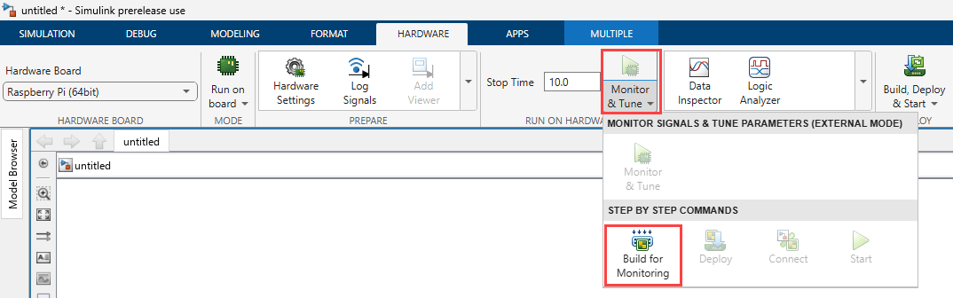
On the Hardware tab of the model, expand the drop-down under Monitor & Tune, and click Build for Monitoring. Simulink builds the model, deploys the executable to Raspberry Pi, and generates an A2L file on the host computer.
Locate, Understand, and Use A2L File
After a successful build, locate the generated AL file on the host computer and verify its contents before importing it into a calibration tool.
Locate A2L File
The A2L file is in the model build folder within your current MATLAB® working directory.
<current_directory>/<model_name>_ert_rtw/<model_name>.a2l
For example, if you name your model as mmyModel and your
working directory is C:\Work, the A2L file is at:
C:\Work\myModel_ert_rtw\myModel.a2l
To open the build folder directly from MATLAB, execute this command in MATLAB Command Window.
cd(fullfile(pwd, '<model_name>_ert_rtw'))Verify that the A2L file was generated and note its full path. Use this path when importing the file into the calibration tool.
A2L File Contents
The A2L file contains all the information a calibration tool needs to communicate with the deployed application on Raspberry Pi.
| Section | Description |
|---|---|
| Memory layout | Addresses, sizes, and record layouts of tunable parameters (characteristics) and observable signals (measurements) in the deployed application. |
| Data types | Variable type information (uint8, int16, single, double, and so on) and computation methods for converting raw values to physical units. |
| XCP communication settings | CAN ID command, CAN ID response, Extended CAN ID, bus speed, byte order, maximum packet sizes — the calibration tool reads these to establish the XCP connection. |
| Metadata | Project name, module description, and ASAM MCD-2 MC version information. |
How Calibration Tools Use A2L File
Discover parameters and signals — The tool reads the A2L file to identify tunable parameters and observable signals in the deployed application.
Establish communication — The tool extracts the XCP communication settings (CAN IDs, transport protocol) to connect to Raspberry Pi without manual configuration.
Data interpretation — The tool uses data type and conversion information to display signals in correct physical units and write parameter values in the correct format.
When to Regenerate A2L File
Rebuild the model to generate an updated A2L file if you:
Add, remove, or rename tunable parameters or observable signals.
Change the CAN ID command, CAN ID response, or Extended CAN ID settings.
Modify the storage class of a parameter or signal.
After rebuilding the model, reload the updated A2L file in the calibration tool before reconnecting to the deployed application.
Connect with Third-Party Calibration Tool
After deployment, the application runs on the Raspberry Pi hardware and is ready to accept XCP on CAN connections. The generated A2L file provides the information required for a calibration tool to identify the available parameters and signals and establish communication with the deployed application.
Import the A2L file into your calibration tool and configure the host-side CAN hardware to begin measurement and calibration. The following sections describe the general workflow for importing an A2L file, configuring communication, and connecting to the deployed application. Refer to your calibration tool documentation for detailed procedures.
Open your calibration tool such as CANape or INCA and create a new project or experiment.
Import the A2L file generated.
Select
XCP on CANas the transport protocol.Configure the host-side CAN hardware in the calibration tool:
Select the CAN hardware interface connected to host computer.
Set the baud rate to match the Raspberry Pi CAN configuration.
Verify that the CAN ID settings in the calibration tool match the values in the A2L file (CAN ID command and CAN ID response).
Connect to Raspberry Pi. The calibration tool sends an XCP connect command on the CAN ID command identifier, and Raspberry Pi responds on the CAN ID response identifier.
Add measurement signals and calibration parameters from the A2L file to your measurement and calibration windows.
Monitor signals in real time and tune parameters as needed.
Save the calibrated parameter values for later use or export.
Troubleshooting
A2L file is not generated
Verify that Host interface is set to
Third party calibration tools.Check the build log in the Diagnostic Viewer for build errors or warnings related to A2L file generation.
Calibration tool cannot connect to Raspberry Pi
Verify that the CAN interface is enabled on Raspberry Pi. Connect to Raspberry Pi using SSH and run
ip link show can0to verify that the interface is upVerify that the CAN ID command and CAN ID response values in the calibration tool match the values configured in the Simulink model and stored in the A2L file.
Verify that the host-side CAN hardware is connected and recognized by the calibration tool.
If you recently changed the XCP on CAN communication settings, rebuild the model and reload the updated A2L file in the calibration tool.
Parameters or signals missing in calibration tool
If you added, removed, or modified parameters or signals after the last build, rebuild the model to generate an updated A2L file.
Reload the updated A2L file in the calibration tool.
Verify that the calibration tool imported the latest version of the A2L file.
See Also
External mode | canChannelList (Vehicle Network Toolbox) | External mode | CAN | CAN
Transmit | CAN
Receive
Topics
- Setup Virtual CAN Interface
- Enable and Configure Raspberry Pi for SPI and CAN Communication Using MCP2515 CAN Controller
- Enable and Configure Raspberry Pi for SPI and CAN FD Communication Using Waveshare 2-CH CAN FD HAT
- Set Up CAN Hardware on Host Computer for XCP on CAN Communication
- Configure Model for XCP on CAN External Mode

