Signal Monitoring and Parameter Tuning over XCP on Serial and TCP/IP
You can use Monitor and Tune (External Mode) action to tune parameters and monitor a Simulink® model running on your target hardware.
Monitor and Tune enables you to tune model parameters and evaluate the effects of different parameter values on model results in real-time. When you change parameter values in a model, the modified parameter values are communicated to the target hardware immediately. You can monitor the effects of different parameter values by viewing the output signals on Sink blocks or in Simulation Data Inspector (SDI). Doing so helps you find the optimal values for performance. This process is called parameter tuning.
Monitor and Tune accelerates parameter tuning. You do not have to rerun the model each time you change parameters. You can also use Monitor and Tune to develop and validate your model using the actual data and hardware for which it is designed. This software-hardware interaction is not available solely by simulating a model.
The support package supports Monitor and Tune simulation over
Serial and TCP/IP communication
interface.
Note
Due to less flash memory, the Nucleo board
STM32 Nucleo
                                    F031K6
doesn't support XCP over Serial and TCP/IP.XCP over Serial for
STM32
                                    Nucleo L053R8
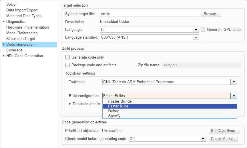
board is supported only withFaster runsas build configuration. The default build configuration forSTM32 Nucleo L053R8board is configured toFaster Runsin Code Generation > Build process > Build configuration.Always ensure to connect the sensor to the board, when performing monitor and tune with sensor block available in the model.
In Universal Measurement and Calibration Protocol (XCP)-based External mode simulation over serial and TCP/IP connections, you can use:
Dashboard blocks: In addition to Sources and Sink blocks, you can use Dashboard blocks to change parameter values and to monitor the effects of parameter tuning. The Dashboard library contains set of blocks using which you can interactively control and visualize the model.
Simulation Data Inspector (SDI): You can inspect and compare data from multiple simulations to validate model designs using Simulation Data Inspector.
Prepare a Simulink Model for External Mode
This section explains how to prepare a Simulink model to run in External mode.
Configure the hardware network as described in Install the Simulink Coder Support Package for STMicroelectronics Nucleo Boards.
Create or open a Simulink model.
Set the Simulation stop time parameter, located to the left of Simulation mode.
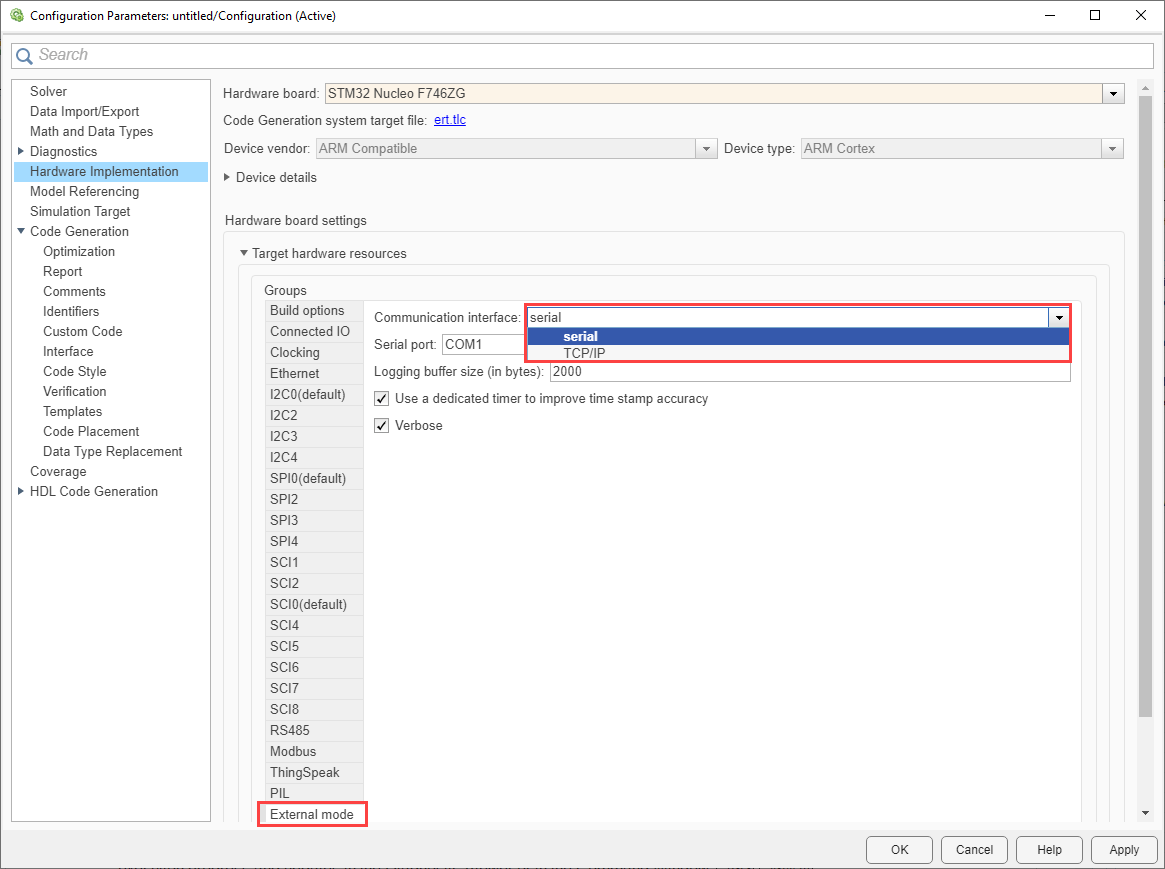
Configure the Model Configuration Parameters for the hardware as described in Model Configuration Simulink Coder Support Package for STMicroelectronics Nucleo Boards. In External mode, set the Communication interface parameter based on the type of External mode simulation to run on the model.

In Communication interface drop-down list, select
SerialorTCP/IP.Specify the Logging buffer size in bytes. Ensure that the logging buffer size is large enough if you are logging more number of signals or logging at faster rates.
Enable the Use a dedicated timer to improve time stamp accuracy parameter if you want to use dedicated timer to log data in real time. If this parameter is not selected, data is logged with simulation time.
Note
To use Display and Scope blocks in a model, ensure that the Use a dedicated timer to improve time stamp accuracy parameter is disabled.
Ensure that the Verbose check box is selected to view the external mode execution progress and updates in the Diagnostic Viewer or in the Command Window.
If you select Communication interface as
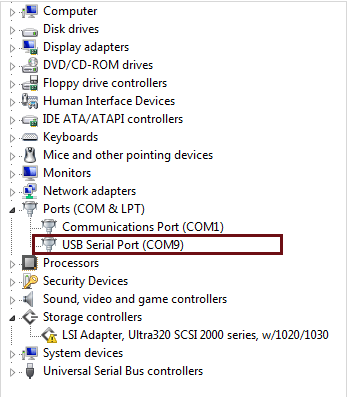
TCP/IP, ensure to configure the Ethernet option. For more information, see Ethernet.Specify the corresponding COM port that the target hardware uses.
To see the list of available COM ports on your computer, select Start > Control Panel > Device Manager > Ports (COM & LPT).

Your model is now ready to perform Monitor and Tune action (External Mode) over serial communication or TCP/IP.
Signal Monitoring and Parameter Tuning of Simulink Model
XCP-Based External Mode Simulation over Serial Connection or TCP/IP
Before you begin, complete the Prepare a Simulink Model for External Mode section.
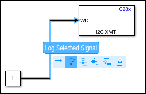
In the Simulink model, identify the signals to be logged for monitoring during simulation. Select the identified signal, open its context menu, and click the icon corresponding to Enable Data Logging.

For instructions on logging the signal using other methods, refer to Simulink documentation. Simulink displays a logged signal indicator
 for each logged signal.
(Optional) Place one or more Sink blocks in the model, and then mark the signals connected to them also for logging. For example, connect Display or Scope blocks and mark the signals connected to them for logging.
To start the simulation,open the Hardware tab and click the Monitor & Tune.

If none of the signals in the model is marked for logging, the MATLAB® Command Window displays a warning message.
You can disregard this warning or mark signals for logging.
After several minutes, Simulink starts running the model on the hardware.
During simulation, when new simulation data becomes available in SDI, the Simulation Data Inspector button
 appears highlighted.
View the simulation output in Sink blocks or in SDI.
Sink blocks – To view the simulation output, double-click the Sink blocks in the model.
SDI – To view the new simulation data, perform these steps:
Click the Simulation Data Inspector button.
A new simulation run appears in the Inspect pane. The Inspect pane lists all logged signals in rows, organized by simulation run. You can expand or collapse any of the runs to view the signals in a run. For more information on signal grouping, see Signal Grouping.
We recommend you use SDI rather than using Sink blocks for the following reasons:
Streaming data to SDI does not store data in memory, making more efficient use of the memory available on the hardware. Sink blocks such as Scope stores data in buffers before sending the data to the host.
Using SDI, you can stream signals from top models and reference models simultaneously. Scope blocks can only log signals from a top-level model.
Change the parameter values in the model. Observe the corresponding changes in the simulation output.
Find the optimal parameter values by making adjustments and observing the results in the Sink blocks.
After you are satisfied with the results, stop the Monitor and Tune action, and save the model.
Note
Monitor and Tune action increases the processing burden of the model running on the board. If the software reports an overrun, stop the Monitor and Tune action.
Stop Monitor and Tune
To stop the model that is running in Monitor and Tune, open the
Hardware tab and click the Stop button ![]() .
.
If the Simulation stop time parameter is set to a specific number of seconds, Monitor and Tune stops when that time elapses.
Troubleshooting
Memory overflow issue during compilation
Description
The following error might occur due to insufficient memory:
ld.exe: ../nucleo_simple.elf section `.text' will not fit in region `FLASH'
ld.exe: region `FLASH' overflowed by 1704 bytes
collect2.exe: error: ld returned 1 exit status
Action
This error shown at linking stage indicates that the memory is insufficient to
fit the code section (.text) in the target memory available.
External Mode simulation requires additional code to enable the communication
between Simulink and the target, which might lead to this code section overflow. To
mitigate this issue, select Faster Runs as the
Build Configuration in the Configuration
Parameters screen. This option compiles the code at
-O3 optimization level, resulting in a smaller code size
which might fit the target memory.
