Selector
R2026bSelect input elements from vector, matrix, or multidimensional signal
Selector block
To add a block to a model, double-click the canvas and start typing the block name. Then, select the block from the list.
Libraries:
Simulink /
Signal Routing
HDL Coder /
Signal Routing
Description
The Selector block extracts selected elements of an input vector, matrix, or multidimensional signal based on specified indices. The extracted signals can be grouped differently than the input signals.
Based on the value you enter for the Number of input dimensions parameter, a table of indexing settings is displayed. Each row of the table corresponds to one of the input dimensions in Number of input dimensions. For each dimension, you define the elements of the signal to work with. Specify a vector signal as a 1-D signal and a matrix signal as a 2-D signal. When you configure the Selector block for multidimensional signal operations, the block icon changes.
For example, assume a 6-D signal with a one-based index mode. The table of the
Selector block dialog box changes to include one row for each
dimension. If you define dimensions as shown in the next table, the output is Y
= U(1:end,2:6,[1 3 5],Idx4:Idx4+7,Idx5,Idx6(1):Idx6(2)), where
Idx4, Idx5, and Idx6 are
the index ports for dimensions 4, 5, and 6. For more information, see Select Elements from Multidimensional Array Using Selector Block.
| Row | Index Option | Index | Output Size |
|---|---|---|---|
| 1 | Select all | ||
| 2 | Starting index (dialog) | 2 | 5 |
| 3 | Index vector (dialog) | [1 3 5] | |
| 4 | Starting index (port) | 8 | |
| 5 | Index vector (port) | ||
| 6 | Starting and ending indices (port) |
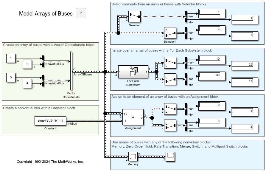
You can use an array of buses as an input signal to a Selector block. For details about defining and using an array of buses, see Group Nonvirtual Buses in Arrays of Buses.
Note
Selector block does not change the dimensionality (number of dimensions) of the input signals. If you need to change the dimensionality of the signal to the dimensions you specify, use Reshape block.
Examples
This example shows two Selector blocks with the same kind of input signals, but two different Index Option settings.
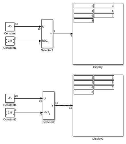
Both Selector blocks select 7 values from the input signal that feeds the input port. The Selector1 block outputs a fixed-size signal, whereas the Selector2 block outputs a variable-size signal whose compiled signal dimension is 10 instead of 7.
The Selector1 block sets Index Option to Index vector (port), which uses the input signal from Constant1 as the index vector. The dimension of the input signal is 7, so the Display block shows the 7 values of the Constant1 block. The Selector2 block sets the Input port size parameter to 10, which is the size of the largest input signal to the Selector2 block.
The Selector2 block also sets the Index Option to Starting and ending indices (port). The output is then set to the size of Input port size parameter (10), even though the size of the input signal is 7.
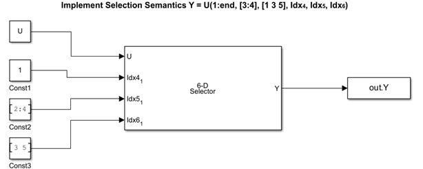
This example shows how to select elements from a multidimensional array using a Selector block. In this example, you use different indexing options of the block to select and extract the elements of a 6-D array.
Open the model.
mdl = "extractmultidimarray.slx";
open_system(mdl)
Configure the Block
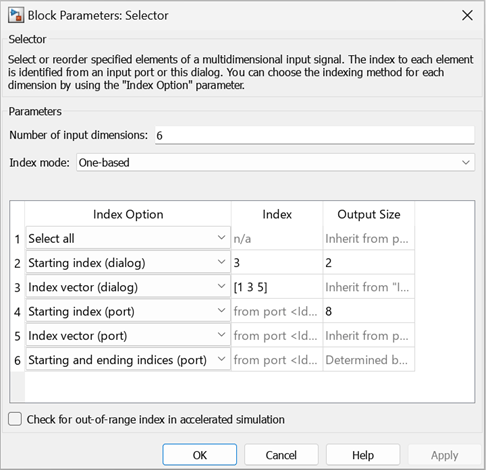
The input array U is a 6-D array with dimensions 6-by-6-by-6-by-9-by-7-by-5 with a one-based index mode. The model loads the input array from the inputSignal file by using model PreLoadFcn callback. You can select elements from each dimension of the array using the following selection semantics and different index options. In this example, one-based index mode is used for the input array. Consequently, the row numbers (first column of the table) directly indicate the dimensions of the input array. For example, row 1 indicates dimension 1 of the input array, and so on.
To extract all of the elements of dimension 1, use
Select All.To extract the third and fourth elements of dimension 2, use
Starting Index (dialog). Set Index column to3and Output Size column to2.To extract the first, third, and fifth element of dimension 3, use
Index vector (dialog). Set Index column to [1 3 5].To extract the first eight elements of dimension 4, use
Starting Index (port). The Constant blockConst1connected to port provides the starting index value1. Set the Output Size column to8.To extract the second, third, and fourth elements of dimension 5, use
Index vector (port). The Constant blockConst2connected to port provides the index value [2:4].To extract a range of elements from dimension 6, use
Starting and ending indices (port). The selection ranges from the third to the fifth element. The Constant blockConst3connected to port provides the range [3 5].
Log signal
Run the simulation and use the To Workspace block to log the signal to the variable Y.
Y = sim(mdl);
Extended Examples
Bounded Variable-Size Signal Basic Operations
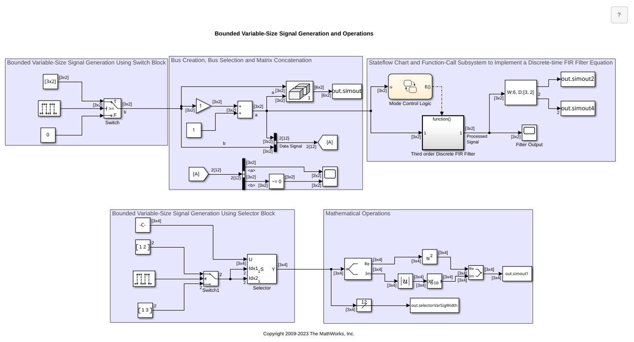
Generate bounded variable-size signals and illustrates some of the operations using those signals. In this example, you generate variable-size signals using the Selector block and the Switch block. The signals are used in math operations, bus creation, bus selection, matrix concatenation and to implement a discrete filter equation.
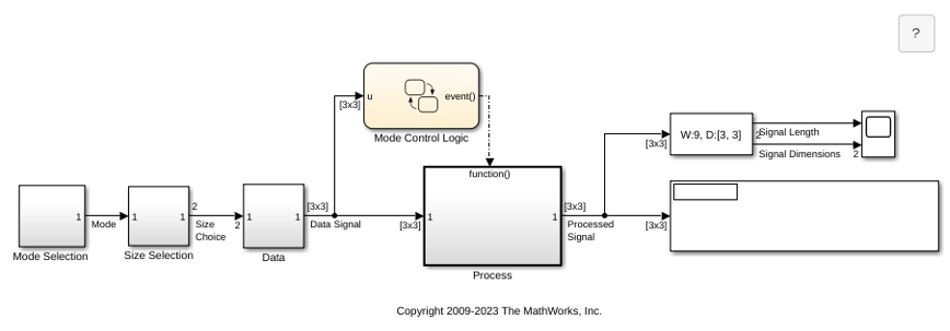
Multimode Variable-Size Signal
Use different operation modes to correspond to different signal sizes.
Limitations
The Index parameter is not tunable during simulation. If the Index Option for a dimension is set to
Index vector (dialog)orStarting index (dialog)and you specify a symbolic value, including aSimulink.Parameterobject, for the corresponding Index in the block dialog box, then the instantaneous value at the start of simulation will be used throughout the simulation, and the parameter will appear as an inlined value in the generated code. See Tune and Experiment with Block Parameter Values. You can adjust the selection index dynamically by using index ports.
Ports
Input
Input signal and source of elements to output signal.
Data Types: single | double | half | int8 | int16 | int32 | int64 | uint8 | uint16 | uint32 | uint64 | Boolean | fixed point | enumerated | bus | image
External port specifying an index for the selection of the corresponding output element.
You can specify integer of custom width (for example, a 15-bit integer
or 23-bit integer) as an index signal value. When you configure the
width of the integer, you must specify the Mode as
Fixed point, with Word
length less than or equal to 65,535,
Slope equal to 1, and Bias
equal to 0. For more information on specifying a fixed-point data type,
see Specify Data Types Using Data Type Assistant.
Dependencies
To enable an external index port, in the corresponding row of the
Index Option table, set Index
Option to Index vector
(port), Starting index
(port), or Starting and ending
indices (port).
Data Types: single | double | int8 | int16 | int32 | uint8 | uint16 | uint32
Output
Output signal generated from selected or reordered elements of input signal.
Data Types: single | double | half | int8 | int16 | int32 | int64 | uint8 | uint16 | uint32 | uint64 | Boolean | fixed point | enumerated | bus | image
Parameters
Specifies the number of dimensions of the input signal.
Programmatic Use
Block Parameter:
NumberOfDimensions
|
| Type: character vector |
Values:
integer
|
Default:
'1'
|
Specifies the indexing mode. If One-based is selected,
an index of 1 specifies the first element of the input vector. If
Zero-based is selected, an index of 0 specifies the
first element of the input vector.
Programmatic Use
Block Parameter:
IndexMode
|
| Type: character vector |
Values:
'One-based' | 'Zero-based'
|
Default:
'One-based'
|
Defines, by dimension, how the elements of the signal are to be indexed. From the list, select:
Select allNo further configuration is required. All elements are selected.
Index vector (dialog)Enables the Index column. Enter the vector of indices of the elements.
Index vector (port)No further configuration is required.
Starting index (dialog)Enables the Index and Output Size columns. Enter the starting index of the range of elements to select in the Index column and the number of elements to select in the Output Size column.
Starting index (port)Enables the Output Size column. Enter the number of elements to be selected in the Output Size column.
Starting and ending indices (port)No further configuration is required.
Using this option results in a variable-size output signal. When you update, the output dimension is set to be the same as the input signal dimension. During execution, the output dimension is updated based on the signal feeding the index.
When logging output signal data, signals not selected are padded with NaN values.
The Index and Output Size columns appear as needed.
Programmatic Use
Block Parameter:
IndexOptionArray
|
| Type: cell array of character vectors |
Values:
{'Select all'} | {'Index vector
(dialog)'} | {'Index vector
(port)'} | {'Starting index
(dialog)'} | {'Starting index
(port)'} | {'Starting and ending indices
(port)'} |
Default:
{'Index vector (dialog)'}
|
For a character vector instead of a cell array of character vectors,
use IndexOptions.
When the Index Option is Index vector
(dialog), enter the index of each element you are
interested in.
When the Index Option is Starting index
(dialog), enter the starting index of the range of
elements to be selected.
Programmatic Use
Block Parameter:
IndexParamArray
|
| Type: cell array of character vectors |
| Values: integers |
Default:
{'[1 3]'}
|
For a character vector instead of a cell array of character vectors,
use Indices.
Specifies the width of the block output signal.
Programmatic Use
Block Parameter:
OutputSizeArray
|
| Type: cell array of character vectors |
| Values: integers |
Default:
{'1'}
|
For a character vector instead of a cell array of character vectors,
use OutputSizes.
Specify the width of the block input signal for 1-D signals. Enter
-1 to inherit from the driving block.
Programmatic Use
Block Parameter:
InputPortWidth
|
| Type: character vector |
Values:
integer
|
Default:
'3'
|
Specify the time interval between samples. To inherit the sample time, set this
parameter to -1. For more information, see Specify Sample Time.
Dependencies
This parameter is visible only if you set it to a value other than
-1. To learn more, see Blocks for Which Sample Time Is Not Recommended.
Programmatic Use
To set the block parameter value programmatically, use
the set_param function.
| Parameter: | SampleTime |
| Values: | "-1" (default) | scalar or vector in quotes |
Select this check box to have Simulink® check during simulation in accelerator or rapid accelerator mode whether any index values are outside the range of valid indices for the relevant dimension of the input signal. If an index is out of range, Simulink stops the simulation and displays an error message.
Note
If you do not select this check box, out-of-range index values could lead to undefined behavior during accelerator or rapid accelerator mode simulation.
Simulink performs this check during normal mode simulation regardless of whether you select this check box.
Dependencies
This parameter is hidden by default. The Selector
block checks for out-of-range index values in accelerator and rapid accelerator simulation
modes by default. This parameter is only enabled and visible when you programmatically set the
RuntimeRangeChecks property to 'off'.
Programmatic Use
Parameter:
RuntimeRangeChecks
|
| Type: character vector |
Values:
'Off' | 'On' |
Default:
'Off'
|
Block Characteristics
Data Types |
|
Direct Feedthrough |
|
Multidimensional Signals |
|
Variable-Size Signals |
|
Zero-Crossing Detection |
|
Extended Capabilities
C/C++ Code Generation
Generate C and C++ code using Simulink® Coder™.
HDL Coder™ provides additional configuration options that affect HDL implementation and synthesized logic.
This block has one default HDL architecture.
| General | |
|---|---|
| ConstrainedOutputPipeline | Number of registers to place at
the outputs by moving existing delays in the design. Distributed pipelining
does not redistribute these registers. The default value is
|
| InputPipeline | Number of input pipeline stages
to insert in the generated code. Distributed pipelining and constrained
output pipelining can move these registers. The default value is
|
| OutputPipeline | Number of output pipeline stages
to insert in the generated code. Distributed pipelining and constrained
output pipelining can move these registers. The default value is
|
| SynthesisAttributes |
Specifies the synthesis attributes for the blocks and block output signals in the model. The generated HDL code contains these attributes. For more information, see SynthesisAttributes (HDL Coder). |
| Native Floating Point | |
|---|---|
| LatencyStrategy | Specify whether to map the blocks in your design to
|
The block supports these data types for HDL code generation:
| Input Port | Dimension | Fixed-Point | Floating-Point | Built-in Integers | Bus | Boolean | Enumerated | Complex Signal |
|---|---|---|---|---|---|---|---|---|
| Port1 | Scalar Vector Matrix (up to 2-D) | Yes | Half Single Double | No | Yes | Yes | Yes | Yes |
The block participates in these HDL optimizations to optimize the speed, and area.
Area Optimization
| Optimization | Description |
|---|---|
| Resource Sharing (HDL Coder) | Resource sharing is an area optimization in which HDL Coder identifies multiple functionally equivalent resources and replaces them with a single resource. |
| Streaming (HDL Coder) | Streaming is an area optimization in which HDL Coder transforms a vector data path to a scalar data path (or to several smaller-sized vector data paths). |
Speed Optimization
| Optimization | Description |
|---|---|
| Specify Distributed Pipelining Settings (HDL Coder) | Distributed pipelining, or register retiming, is a speed optimization that moves existing delays in a design to reduce the critical path while preserving functional behavior. |
| Clock-Rate Pipelining (HDL Coder) | Clock-rate pipelining is an optimization framework in HDL Coder that allows other speed and area optimizations to introduce latency at the clock rate. |
| Specify Adaptive Pipelining Settings (HDL Coder) | Adaptive pipelining optimization creates patterns or combination of blocks with registers that can improve the achievable clock frequency and reduce the area usage on the FPGA boards by inserting pipeline registers to the blocks in your design. |
PLC Code Generation
Generate Structured Text code using Simulink® PLC Coder™.
Fixed-Point Conversion
Design and simulate fixed-point systems using Fixed-Point Designer™.
Version History
Introduced before R2006aStarting in R2026b, the Selector and Assignment
blocks check for out-of-range index values in accelerator and rapid accelerator
simulation modes by default. The dialog box Check for out-of-range index
in accelerated simulation parameter for the Selector
and Assignment blocks is now hidden and can only be programmatically
enabled by using the RuntimeRangeChecks property.
If you load an existing model with these checks turned off, a warning appears stating that the .setting is not recommended. The model continues to run.
Starting in R2023a, you can customize the width of the integer that you use to specify the index signal value for the Selector block.
Starting in R2023a, a Selector block that is configured to accept a
1-D variable-size input signal, supports Index vector
(dialog) and Starting index (dialog) as
the Index Option.
This enhancement allows you to choose from all the available Index Option settings when you configure the Selector block to accept a1-D variable-size input signal.
See Also
MATLAB Command
You clicked a link that corresponds to this MATLAB command:
Run the command by entering it in the MATLAB Command Window. Web browsers do not support MATLAB commands.
Select a Web Site
Choose a web site to get translated content where available and see local events and offers. Based on your location, we recommend that you select: .
You can also select a web site from the following list
How to Get Best Site Performance
Select the China site (in Chinese or English) for best site performance. Other MathWorks country sites are not optimized for visits from your location.
Americas
- América Latina (Español)
- Canada (English)
- United States (English)
Europe
- Belgium (English)
- Denmark (English)
- Deutschland (Deutsch)
- España (Español)
- Finland (English)
- France (Français)
- Ireland (English)
- Italia (Italiano)
- Luxembourg (English)
- Netherlands (English)
- Norway (English)
- Österreich (Deutsch)
- Portugal (English)
- Sweden (English)
- Switzerland
- United Kingdom (English)


