Unbounded Variable-Size Signal Basic Operations
This example shows how to use unbounded variable-size signals in Simulink® modeling. For more information about the general concept of unbounded variable-size signals, see Unbounded Variable-Size Signals.
This model describes how to configure blocks to use unbounded variable-size signals.
open_system('ex_boundedsignals')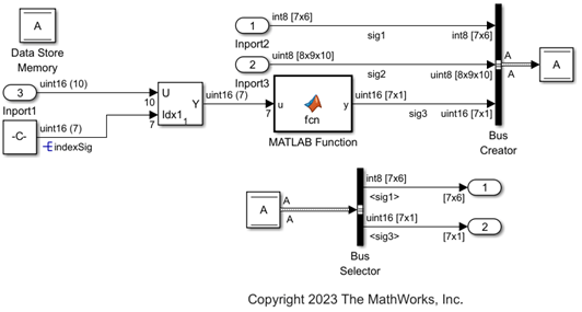
The following sections describe how to configure the Inport block, MATLAB Function block, Simulink.Signal object and Simulink.Bus object to use unbounded variable-size signals.
Configure Inport Block to Generate Unbounded Variable-Size Signals
To generate unbounded variable-size signals from Inport blocks, in the block dialog box:
On the Signal Attributes tab, set the appropriate values of Port dimensions as
Inf. Set Variable-size signal toYesto allow variable-size signals.On the Execution tab, set the Sample time to a discrete rate and clear the Interpolate data check box.
In this example:
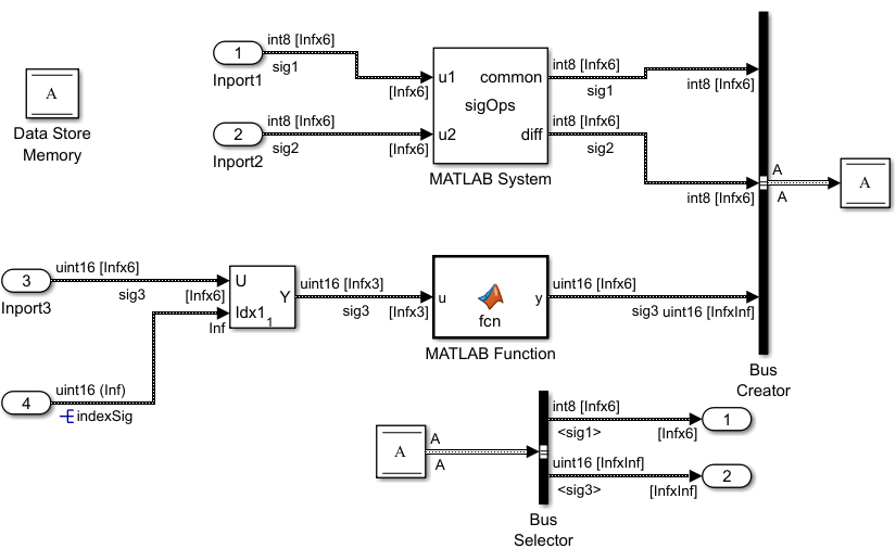
For the
Inport1andInport2blocks connected to the input portsu1andu2, respectively, of the MATLAB System block, on the Signal Attributes tab, set the Port dimensions parameter to[Inf 6], and set the Variable-size signal toYes. On the Execution tab, set the Sample time value to1, and clear the Interpolate data check box. Click Apply and OK.For the
Inport3block connected to the input port of the Selector block, on the Signal Attributes tab, set the Port dimensions parameter to[Inf 6], and set the Variable-size signal toYes. On the Execution tab, set the Sample time value to1, and clear the Interpolate data check box. Click Apply and OK.


To use an unbounded variable-size signal as index signal to the Selector block, replace the Constant block with an Inport block. Configure the Inport block to generate the index signal with dimension Inf, data type uint16 and sample time 1. Click Apply and OK.
Right-click on the signal named indexSig and select Properties > Signal name must resolve to Simulink signal object. Click Apply and OK.
For the Selector block, in the Block Parameters dialog box, select Number of input dimensions as 2, set Index vector (dialog) value to [3 4 5]. Click Apply and OK.
Configure MATLAB Function Block for Unbounded Variable-Size Signals
Specify the size of a variable-size input/output signal associated with the MATLAB Function block. To interactively configure the MATLAB Function block, in the Simulink Editor, on the Modeling tab, from the Design gallery, select Model Explorer. From the Model Explorer window, select the MATLAB Function. Set the dimension in Size to [Inf 6] and select Variable size. Click Apply to apply the changes.

Configure MATLAB System Block and System Objects for Unbounded Variable-Size Signals
The MATLAB System block uses the System object® sigOps that adds and computes difference between two signals. While configuring the System Object® for unbounded variable-size signals, set the flag for isOutputFixedSizeImpl to false and change the output dimensions for getOutputSizeImpl to [Inf 6].

Configure Simulink.Signal Object as Unbounded Variable-Size Signal
Specify the size of a variable-size Simulink.Signal object as unbounded. To programmatically configure the signals, in the Simulink Editor, on the Modeling tab, select Model Settings > Model Properties. In the Model Properties dialog box, on the Callbacks tab, select PreLoadFcn to edit the Simulink.Signal object properties.
For the signal object:
Set
Dimensionsvalue toInf.Set
DimensionsModetoVariable.
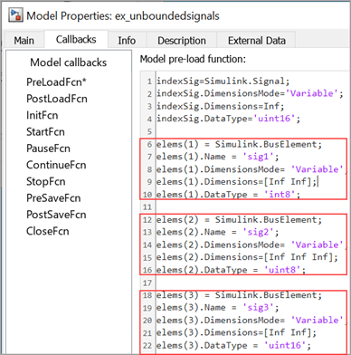
Configure Simulink.Bus Object as Unbounded Variable-Size Signals
Specify the size of a variable-size Simulink.Bus object as unbounded. To programmatically configure the bus elements, in the Simulink Editor, on the Modeling tab, select Model Settings > Model Properties. In the Model Properties dialog box, on the Callbacks tab, select PreLoadFcn to edit the Simulink.BusElement object properties.
For each bus element:
Set appropriate dimensions to infinity by setting
Dimensionsvalue toInf.Set
DimensionsModetoVariable.
Click Apply and OK.
Configure Data Store for Unbounded Variable-Size Signals
Check if the Data type is set to Bus:A on the Signal Attributes tab of the Data Store Memory block dialog box.
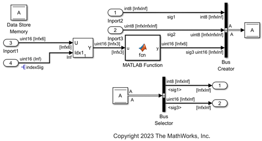
Compile the Model and Verify Signal Dimensions
Once you configure the blocks and Simulink objects, save (Ctrl+S) the model in the working folder and close it. Reopen the model for the updated properties of Simulink.BusElement and Simulink.Signal objects to be effective.
Update (Ctr+D) the model. Verify the signal dimensions with this image.
Set Model Configuration Parameters for Simulation
In the Simulink Editor, on the Modeling tab, click Model Settings. In the Configuration Parameters dialog box:
On the Solver tab, check that the Solver is set to
autoordiscrete.On the Data Import/Export tab, check that the Save Format is set to
Dataset.On the Simulation Target tab, set Language as
C++. In Advanced parameters section, check that Dynamic memory allocation in MATLAB functions is selected.
Set Up Data Logging
To log the output signals from the Data Store Read block, use the Outport block. In this case, the output signals sig1 and sig3 are Simulink bus elements.
See Also
Selector | MATLAB Function | MATLAB System | Bus Creator | Bus Selector | Inport