Mitigate GPS Errors in UAV Reference Tracking Using Disturbance Compensation
This example shows how to track the reference trajectory in a quadcopter in the presence of GPS reading errors. This is achieved using disturbance compensation in the position control loop for tracking in the X and Y directions. The disturbance introduced by the GPS errors is estimated using the Extended State Observer block.
Getting Started
Open the UAVReferenceTracking project file and Simulink® model.
prj = openProject("UAVDisturbanceCompensation/UAVDisturbanceCompensation.prj");
open_system(mdl);
Reference Tracking with GPS Errors
To achieve reference tracking for a quadrotor UAV, this example uses the position, attitude, and altitude controllers tuned as shown in the Tune Control Design for VTOL UAV in Hover Configuration (UAV Toolbox) example. This example injects error signals in the GPS measurement for the X and Y coordinates. This represents situations like multipath errors in GPS data, false data injections, or sensor faults and causes disturbances of high magnitude in the sensor measurements.
Simulation of the UAV while tracking a constant X and Y reference shows the effect an incorrect GPS position measurement has on the actual position of the UAV. The GPSErrorType = 3 modifies the sensor measurement between 20 and 30 seconds to report false UAV position.
open_system(mdl);
enableDisturbanceCompensation = false; %#ok<*NASGU>
setupHoverManual();
GPSErrorType = 3;
simTimeParam.setValue(50);
simout = sim(mdl);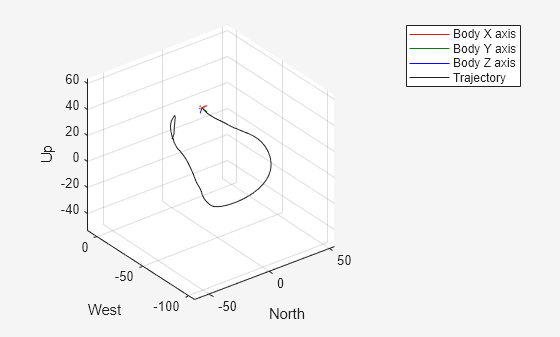
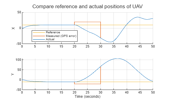
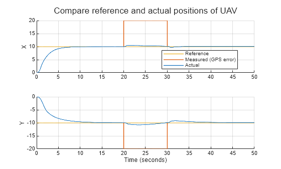
Plotting the reference and the true position of the UAV, along with the incorrect GPS measurements, shows that the closed loop control is unable to track the reference position, and the errors lead to large deviation in the actual UAV position. In such a scenario, the UAV position cannot be controlled using the standard reference tracking controllers and it will be unable to track the mission path.
exampleHelperPlotXYPositionInTime(simout);
Disturbance Compensation
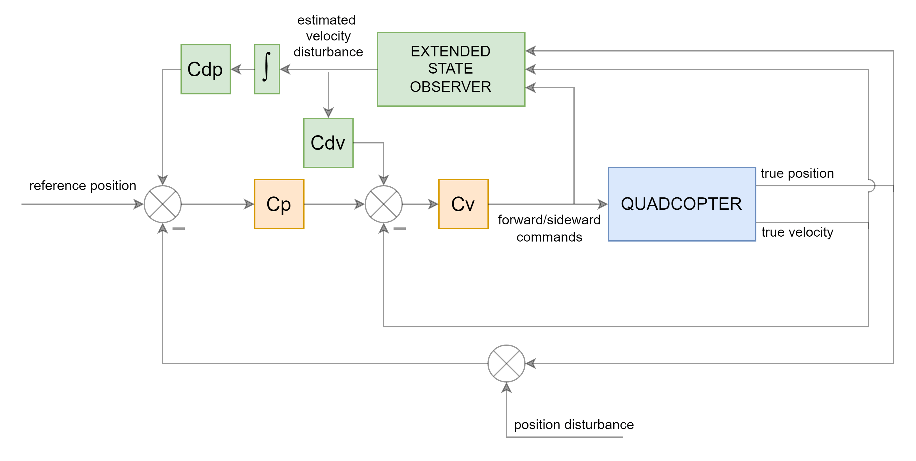
You can estimate the errors in sensor measurements as unknown disturbances using the Extended State Observer block. The estimated disturbance can be used to compensate for the errors in the horizontal position control loop. A basic motion model describing the position and velocity is used to specify the system dynamics in the ESO block.
The output of the ESO, , is the estimated velocity disturbance that affects the computation of in the state equation. This can be integrated to estimate the position error introduced in the GPS measurements. You use thresholding to prevent accumulation of small disturbances due to sudden change in trajectory or wind in the position loop.
The model is defined in the block parameters equivalent to the model sys and observer gains are defined as follows.
A = [1 0.005; 0 1];
B = [0; 1];
C = eye(2);
D = 0;
sys = ss(A,B,C,D,0.005);

Bd = [1; 0];
L = exampleHelperComputeObserverGain(sys,Bd,10,0.1,0.005);
The disturbance compensation is implemented in the XYController subsystem that generates the forward and sideways commands based on the error in X and Y.
open_system('QuadcopterController/Low level controller/Multicopter Controller/Horizontal Position Control/XY Controller');Simulate the UAV with disturbance compensation and the same GPS errors.
setupHoverManual();
GPSErrorType = 3;
enableDisturbanceCompensation = true;
simTimeParam.setValue(50);
simout = sim(mdl);
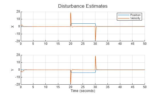
The following plots show the estimated disturbances. Even though the dynamics specified are based on a linear approximation of the plant, the estimated position disturbance follows the errors in GPS measurements (between 20 to 30 seconds) closely. The value is scaled due to inaccuracy of the plant approximation and is compensated for by the designed gain in the disturbance compensation loops.
exampleHelperPlotDisturbanceEstimates(simout);
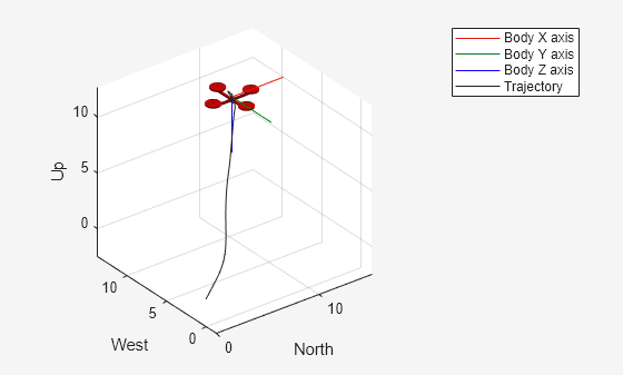
The actual position of the UAV shows that the UAV now tracks the reference position with small deviations.
exampleHelperPlotXYPositionInTime(simout);
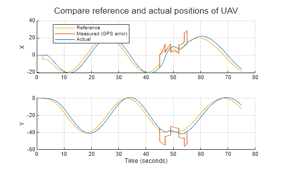
Trajectory Tracking with Disturbance Compensation
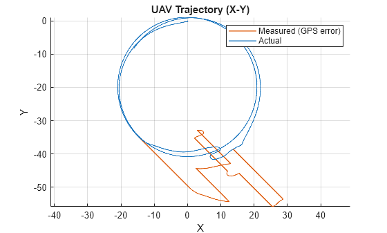
Simulate a hover mission for the UAV, tracking an orbit, with disturbances representing a multipath GPS error. The disturbance compensation ensures that the UAV does not deviate from the orbital path even in the presence of these high amplitude errors.
setupHoverOrbitMission();
GPSErrorType = 2;
enableDisturbanceCompensation = true;
simTimeParam.setValue(75);
simout = sim(mdl);
exampleHelperPlotXYPositionInTime(simout);
exampleHelperPlotXYTrajectory(simout);
Summary
In this example, you used the Extended State Observer block to estimate the disturbance introduced by GPS errors in a UAV with closed loop position control. The errors could be introduced as part of multipath GPS measurements, sensor failures or false data injection in a susceptible communication channel. Adding disturbance compensation loops for position and velocity based on the estimated disturbances results in the UAV being able to track the reference trajectory even in the presence of high amplitude errors.
close_system('QuadcopterGPSErrorMitigation',0);
close_system('QuadcopterController',0);
See Also
Extended State Observer | Disturbance Compensator | Active Disturbance Rejection Control