Response Optimization with Simscape Models
R2026bThis example shows how to tune the value of a resistor and maximize the power transferred from one part of an electric circuit to another by using the Response Optimizer app. It uses an electric circuit which is entirely modeled using Simscape™ and does not have any Simulink® signals. The example shows Simulink Design Optimization™ directly interacting with Simscape. For example, you can specify the power-transfer requirement by clicking on the corresponding Simscape block.
Open the Simulink model.
open_system('sdoImpedanceMatch')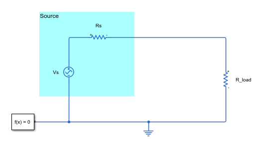
The source resistance, Rs, is 50 ohms. To maximize the power transferred from the source to the load, you adjust the load resistance parameter, R_load.
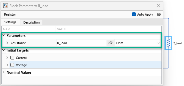
To open the Response Optimizer app from the model, in the Simulink model window, in the Apps gallery, click Response Optimizer.
Set Up the Optimization Problem
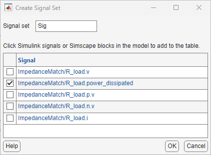
To maximize the power transferred to the load, create a new signal property requirement. In the Response Optimization tab, in the New drop-down list, select Signal Property. To specify the signal associated with the requirement, in the Create Requirement dialog box, in the Select Signals area, click  . In the model, click the load resistor,
 R_load. This populates the Create Signal Set dialog box with the Simscape variables possible for the load resistor. Select the power dissipated and click OK.
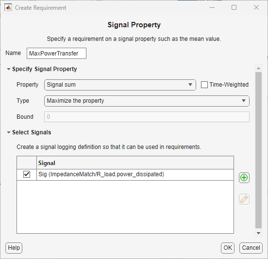
In the Create Requirement dialog box, rename the requirement as MaxPowerTransfer. In the Specify Signal Property area, in the Property drop-down list, select Signal sum, and in the Type drop-down list, select Maximize the property.
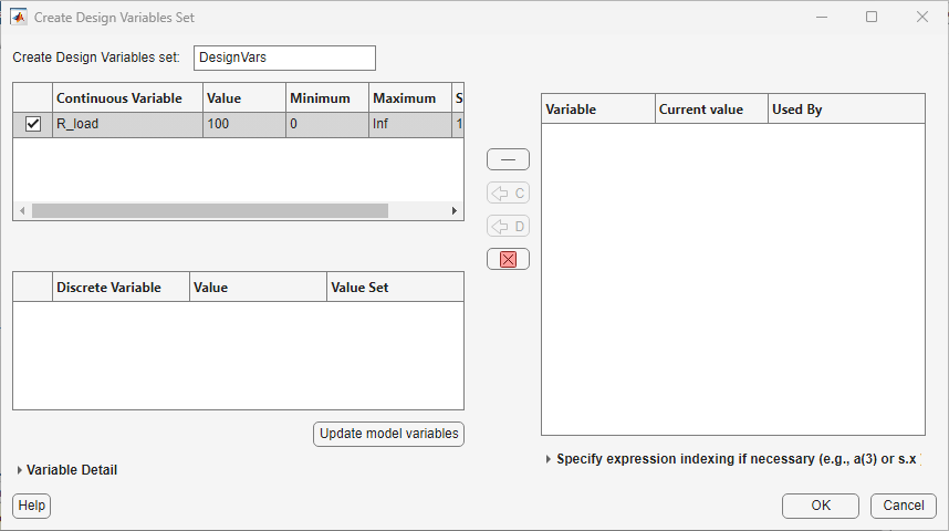
In addition to specifying that the goal of the optimization is to maximize the power transferred to the load, you also need to specify the design variables to tune to achieve that goal. In the Response Optimization tab, in the Design Variables Set drop-down list, select New. In the Create Design Variables Set dialog box, click the variable R_load, and click  to select
 R_load as a continuous design variable. Since the resistance cannot be negative, in the top left table, specify the value of Minimum as 0 and click OK.
Optimize the Model
In the Response Optimization tab, click Optimize. This varies the design variable, R_load, over multiple iterations. The power transferred from the source to the load increases with each iteration until it reaches a maximum. In the Response Optimization tab, in the Add Plot drop-down list, select Parameter Trajectory. Two plots, the value of the design variable (R_load) over time and the value of the maximum power transferred over time, appear in the app. Adjust the tabs of all the plots so that you can view them together.
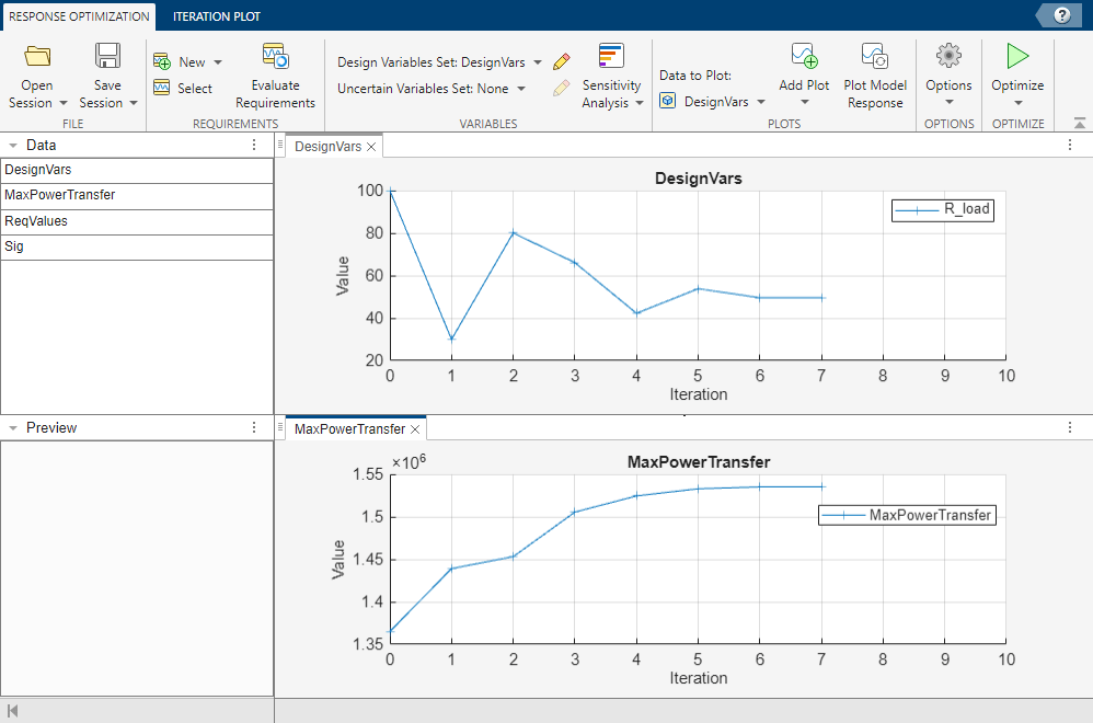
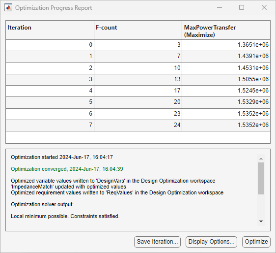
By the end of the optimization, you can see that R_load has a value of 50 ohms, which is the same as the source resistance, Rs. This agrees with the long established result that for maximum power transfer, the load impedance should match the source impedance. In this case, you can find the optimal load resistance analytically without performing numerical simulation. However, in many applications, finding an analytical solution is not feasible and numerical methods are necessary.
So in this example, you can see that when the optimization requirements are connected with Simscape signals, Simulink Design Optimization interacts directly with Simscape.

