Main Content

Belt-Cable Properties

General characteristics of the cord of a pulley system

  • Belt-Cable Properties block

Libraries:
Simscape / Multibody / Belts and Cables

Description

The Belt-Cable Properties block sets the attributes of a pulley cord, among them its geometry and color, as well as its alignment constraints. For the purpose of visualization, the cord is treated as a one-dimensional line with color and opacity. Circular arc segments straddle the pulleys and straight line segments bridge the distances between the arcs.

By default, the cord can enter and exit a drum—pulley or spool—at an angle to its center plane. This angle can vary during simulation—for example, due to translation of the drum on a prismatic joint. While the contact point is always in the center plane of the drum, the drum can move when mounted on a joint. Use this strategy to model, for example, the winding of a cord on a spool and the fleet angle of the same (denoted θ in the figure).
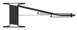
The cord can also be constrained to enter and exit a drum in the center plane of that drum. The assembly may still be three-dimensional, with different pulleys on different planes, but only as long as the contact angles are each zero. Set the Drum Belt-Cable Alignment block parameter to Monitored Planar to enforce this constraint. (Because the constraint is monitored, the simulation stops with an error if a contact angle should be other than zero.)

Other attributes are set automatically by modeling assumptions and calculations. Among the assumptions are those of a massless cord that is both inextensible and always taut. Length is determined at the moment of assembly and fixed thereafter. Its value is consistent with a cord that precisely spans the pulley system as arranged in its initial configuration.

That configuration depends on the starting positions of the various joints in a model. These are matched where feasible to the state targets specified in the joint blocks. It is possible to use those targets to set the length of the cord and to guide the placement of its ends—for example to apply an initial rotation to a spool or an initial translation to a load-bearing anchor.
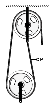
The belt-cable port (P) identifies the cord characterized by this block. It matters little where in a belt-cable network the port connects. It is important, however, that each belt-cable network in a model contain one instance of this block. A belt-cable network is distinct from another if there is no belt-cable connection line between the two.

The visualization of the cord is by default on but it can be suppressed in the block. If it is on, you can click any point on a cord to highlight its entire length. Look in the tree view pane for the name of the Belt-Cable Properties block associated with the selected cord—the block name is identified there. Right-click the block name and select Go To Block if necessary to update the cord visualization properties.

Examples

Ports

Belt-Cable

expand all

Attachment point for the belt-cable network whose properties this block aims to specify.

Parameters

expand all

Type of alignment allowed between the cord and the center plane of a drum (whether pulley or spool). Select Unrestricted to enable the cord to enter and exit the drum center plane at an angle. The entry and exit angles can differ during simulation. Select Monitored Planar to require that the cord always enter and exit a drum in line with its center plane. If at any time the contact angle differs from zero, the simulation then stops with an error.

Means by which to show the cord in a model visualization. The default setting corresponds to a pitch line that arcs around each pulley and spool at the pitch radii specified in their respective blocks. The line segments are circular in the ranges of contact between the cord and pulley or spool; they are straight in the distances between the arcs.

Parameterizations for specifying visual properties. Select Simple to specify Diffuse Color and Opacity. Select Advanced to specify more visual properties, such as Specular Color, Ambient Color, Emissive Color, and Shininess.

Dependencies

To enable this parameter, set Type to From Geometry or Marker.

Color of the graphic under direct white light, specified as an [R G B] or [R G B A] vector on a 0–1 scale. An optional fourth element (A) specifies the color opacity on a scale of 0–1. Omitting the opacity element is equivalent to specifying a value of 1.

Dependencies

To enable this parameter, set:

  1. Type to From Geometry or Marker

  2. Visual Properties to Simple

Graphic opacity, specified as a scalar in the range of 0 to 1. A scalar of 0 corresponds to completely transparent, and a scalar of 1 corresponds to completely opaque.

Dependencies

To enable this parameter, set:

  1. Type to From Geometry or Marker

  2. Visual Properties to Simple

Color of the light due to diffuse reflection, specified as an [R,G,B] or [R,G,B,A] vector with values in the range of 0 to 1. The vector can be a row or column vector. The optional fourth element specifies the color opacity. Omitting the opacity element is equivalent to specifying a value of 1.

The diffuse color reflects the main color of the rendered solid and provides shading that gives the rendered object a three-dimensional appearance.

Dependencies

To enable this parameter, set:

  1. Type to From Geometry or Marker

  2. Visual Properties to Advanced

Color of the light due to specular reflection, specified as an [R,G,B] or [R,G,B,A] vector with values in the range of 0 to 1. The vector can be a row or column vector. The optional fourth element specifies the color opacity. Omitting the opacity element is equivalent to specifying a value of 1. This parameter changes the color of the specular highlight, which is the bright spot on the rendered solid due to the reflection of the light from the light source.

Dependencies

To enable this parameter, set:

  1. Type to From Geometry or Marker

  2. Visual Properties to Advanced

Color of the ambient light, specified as an [R,G,B] or [R,G,B,A] vector with values in the range of 0 to 1. The vector can be a row or column vector. The optional fourth element specifies the color opacity. Omitting the opacity element is equivalent to specifying a value of 1.

Ambient light refers to a general level of illumination that does not come directly from a light source. The Ambient light consists of light that has been reflected and re-reflected so many times that it is no longer coming from any particular direction. You can adjust this parameter to change the shadow color of the rendered solid.

Dependencies

To enable this parameter, set:

  1. Type to From Geometry or Marker

  2. Visual Properties to Advanced

Color due to self illumination, specified as an [R,G,B] or [R,G,B,A] vector in the range of 0 to 1. The vector can be a row or column vector. The optional fourth element specifies the color opacity. Omitting the opacity element is equivalent to specifying a value of 1.

The emission color is color that does not come from any external source, and therefore seems to be emitted by the solid itself. When a solid has an emissive color, the solid can be seen even if there is no external light source.

Dependencies

To enable this parameter, set:

  1. Type to From Geometry or Marker

  2. Visual Properties to Advanced

Sharpness of specular light reflections, specified as a scalar number on a 0–128 scale. Increase the shininess value for smaller but sharper highlights. Decrease the value for larger but smoother highlights.

Dependencies

To enable this parameter, set:

  1. Type to From Geometry or Marker

  2. Visual Properties to Advanced

Extended Capabilities

C/C++ Code Generation
Generate C and C++ code using Simulink® Coder™.

Version History

Introduced in R2018a

Go to top of page