AD936x Transmitter
Libraries:
SoC Blockset Support Package for AMD FPGA and SoC Devices /
MPSoC /
ZCU102
SoC Blockset Support Package for AMD FPGA and SoC Devices /
Zynq-7000 /
ADI RF SOM
SoC Blockset Support Package for AMD FPGA and SoC Devices /
Zynq-7000 /
ZC706
SoC Blockset Support Package for AMD FPGA and SoC Devices /
Zynq-7000 /
ZedBoard
Description
Add-On Required: This feature requires the SoC Blockset Support Package for AMD FPGA and SoC Devices add-on.
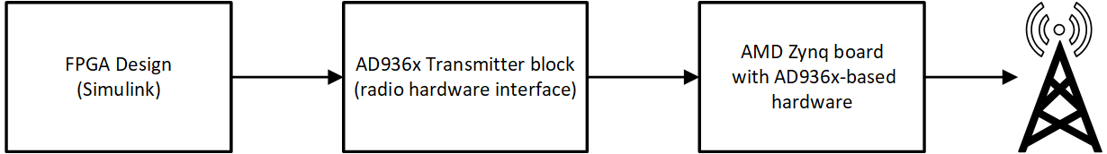
The AD936x Transmitter block sends data to an AD936x-based Zynq® radio hardware.
You can use the AD936x Transmitter block to simulate and develop various software-defined radio (SDR) applications. This diagram shows the conceptual overview of transmitting and receiving radio signals in Simulink® using the SoC Blockset™ Support Package for AMD FPGA and SoC Devices. Simulink interacts with the AD936x Transmitter block to send data to the radio hardware.
Examples

Transmit Data on Multiple Channels Using Simulink Block
This model is set up to transmit data on two channels. The Channel mapping parameter of the E3xx Transmitter block is set to [1 2]. The underflow port is disabled by clearing the Enable output port for underflow indicator parameter. The Sine Wave Channel 1 block is configured to generate an 8 kHz sine wave. The Sine Wave Channel 2 block is configured to generate a 1 kHz sine wave. Both sine waves are sampled at 1 MHz. When you run this model, the E3xx Transmitter block sends the generated and combined sine waves through the air. You can inspect the generated data in the Spectrum Analyzer blocks.
Limitations
To use this block, in the hardware setup, select one of these boards and add-on cards.
Analog Devices® RF SOM
Xilinx® Zynq ZC706 Evaluation Kit with Analog Devices FMCOMMS2/3/4 RF card
ZedBoard™ with Analog Devices FMCOMMS2/3/4 RF card
Zynq UltraScale+™ MPSoC ZCU102 Evaluation Kit with Analog Devices FMCOMMS2/3/4 RF card
Ports
Input
Input signal sent to the radio hardware, specified as a complex matrix. The number of columns in the matrix depends on the number of channels in use, as specified by the radio channel properties. Each column corresponds to a channel of complex data sent via one channel. In single-channel mode, the number of elements in a column must be even.
This port supports complex values with these data types:
16-bit signed integers — Since the AD9361/AD9364 RF chip has a 12-bit DAC, only the 12 most significant bits of the I and Q samples are used.
Single-precision floating point — Complex values in the range of [–1, 1]. Since the AD9361/AD9364 RF chip has a 12-bit DAC, numbers of magnitude less than 0.0625 are lost.
Double-precision floating point — Complex values in the range of [–1, 1]. since the AD9361/AD9364 RF chip has a 12-bit DAC, numbers of magnitude less than 0.0625 are lost.
When you select the Concatenated complex signal parameter,
the data type is represented as uint32, rather than
int16 complex.
Dependencies
To enable this port, set the Data source select parameter
to Input port.
Data Types: int16 | single | double
Complex Number Support: Yes
Valid data indicator, returned as one of these values:
1— Indicates that the input data is valid for transmission to the radio hardware.0— Indicates that the input data is not valid.
Data Types: Boolean
External RF center frequency, specified as a nonnegative finite scalar. The valid center frequency range is from 70 MHz to 6 GHz.
Dependencies
To enable this port, set the Simulation output parameter to
To connected
                  IO
, and set the Source of center
frequency parameter to Input port.
Data Types: double
External gain source, specified as a numeric scalar or a 1-by-2 numeric vector. The valid gain range is –89.75 dB to 0 dB. The resolution is 0.25 dB.
Set the gain based on the radio channel configuration.
For a single channel, specify the gain as a scalar.
For two channels that use the same gain value, specify the gain as a scalar. The block applies the gain by scalar expansion.
For two channels that use different gain values, specify the gain as a 1-by-2 vector. The
ith element of the vector is applied to theith channel specified by the radio channel properties.
Dependencies
To enable this port, set the Simulation output parameter to
To connected IO, and set the Source of
gain parameter to Input port.
Data Types: double
Output
Output signal simulating the radio hardware, specified as a complex matrix. The number of columns in the matrix depends on the number of channels in use, as specified by the by radio channel properties. Each column corresponds to a channel of complex data received on one channel.
When you select the Concatenated complex signal parameter,
the datatype is represented as uint32, rather than
int16 complex.
Dependencies
To enable this port, set the Simulation output parameter to
To output port.
Data Types: int16 | single | double
Complex Number Support: Yes
Data discontinuity flag, returned as one of these values:
1indicates the presence of underflow resulting in noncontiguous data.0indicates no underflow.
You can use this port as a diagnostic tool to determine real-time operation of the AD936x Transmitter block. If your model is not running in real time, increase the frame size to approach or achieve real-time performance. Alternatively, you can decrease the baseband sampling rate.
Note
Running the block for the first time initializes the radio. Because this initialization can result in an underflow, ignore the underflow output port value of the first run.
Dependencies
To enable this port, on the Main tab, set the
Simulation output parameter to To connected
IO, and select the Enable output port for underflow
indicator parameter.
Data Types: Boolean
Parameters
The
AD936x Transmitter block supports up to
two
channels to send data to the AD936x-based Zynq radio hardware. Use the radio channel properties to indicate whether to use a
single channel or
two
channels. For each channel in the input signal, data, you can set the
Gain (dB) parameter independently, or you can apply the same setting to
all channels. If you select direct digital synthesis (DDS) transmission for the Data
source select parameter, you can also set all DDS-based parameters independently
(in connected IO mode only). All other parameter values are applied to each
channel in use.
To check connectivity between the block and the radio hardware, and to synchronize radio settings between them, on the Main tab, click Info.
When you set block parameter values, the AD936x Transmitter block first checks that the values have the correct data types. If the values pass those checks, the values can still be out of range for the radio hardware. In that case, the radio hardware sets the actual value as close to the specified value as possible. When you next synchronize the block with the radio hardware by clicking Info, a dialog box displays the actual values.
Select source for simulation input:
Terminator— the output data produced by this block is terminated. Use this option when building the system, and simulating data is not required.To output port— this option adds an output port data to the block. — Since the AD9361/AD9364 RF chip has a 12-bit DAC, only the 12 most significant bits of the I and Q samples are used.To connected IO— Use this option to send live output data to the board.
To check connectivity between the block and the radio hardware, and to synchronize radio settings between them, on the Main tab, click Info.
When you set block parameter values, the AD936x Transmitter block first checks that the values have the correct data types. If the values pass those checks, the values can still be out of range for the radio hardware. In that case, the radio hardware sets the actual value as close to the specified value as possible. When you next synchronize the block with the radio hardware by clicking Info, a dialog box displays the actual values.
If a parameter is listed as tunable, then you can change its value during simulation.
Main
Select this option to enable data transmission on channel 1.
Select this option to enable data transmission on channel 2.
The RF chip of the radio hardware determines the number of channels you can use for receiving data.
| Supported Radio Hardware | RF Chip | Number of Channels | Supported RF Ports |
|---|---|---|---|
ADI RF SOM ZC706 and FMCOMMS2 or FMCOMMS3 ZedBoard and FMCOMMS2 or FMCOMMS3 ZCU102 and FMCOMMS2 or FMCOMMS3 | AD9361 | 2 | TX1A, RX1A, TX2A, RX2A |
ZC706 and FMCOMMS4 ZedBoard and FMCOMMS4 ZCU102 and FMCOMMS4 | AD9364 | 1 | TXA, RXA |
Select this option when the input and output signal are represented as
unit32 instead of a complex number with int16
for real and int16 for imaginary.
IP address of the radio hardware, specified as a dotted-quad expression.
This parameter must match the physical IP address of the radio hardware assigned during hardware setup. For more information, see Set Up AMD FPGA and SoC Devices. If you configure the radio hardware with an IP address other than the default, update Radio IP address accordingly.
Dependencies
To enable this parameter, set the Simulation output
parameter to To connected IO.
Click this button to check connectivity between the block and the radio hardware, and to synchronize radio settings between them.
When you set block parameter values, the AD936x Transmitter block first checks that the values have the correct data types. If the values pass those checks, the values can still be out of range for the radio hardware. In that case, the radio hardware sets the actual value as close to the specified value as possible. When you next synchronize the block with the radio hardware by clicking Info, a dialog box displays the actual values.
Dependencies
To enable this parameter, set the Simulation input
parameter to From connected IO.
Source of center frequency, specified as one of these options:
Dialog— Set the center frequency by using the Center frequency (Hz) parameter.Input port— Set the center frequency by using the center frequency input port.
Dependencies
To enable this parameter, set the Simulation output
parameter to To connected IO.
RF center frequency in Hz, specified as a nonnegative scalar. The valid range for center frequency is 70 MHz to 6 GHz.
Tunable: Yes
Dependencies
To enable this parameter, set the Simulation output
parameter to To connected IO, and set the
Source of center frequency parameter to
Dialog.
Data Types: double
Dialog— Specify the gain by using the Gain (dB) parameter.Input port— Specify the gain by using the gain input port.
Dependencies
To enable this parameter, set the Simulation output
parameter to To connected IO.
Gain in dB, specified as a numeric scalar or a 1-by-2 numeric vector. The valid gain range is –89.75 dB to 0 dB. The resolution is 0.25 dB.
Set the gain based on the radio channel configuration.
For a single channel, specify the gain as a scalar.
For two channels that use the same gain value, specify the gain as a scalar. The block applies the gain by scalar expansion.
For two channels that use different gain values, specify the gain as a 1-by-2 vector. The ith element of the vector is applied to the ith channel specified by the radio channel properties.
Tunable: Yes
Dependencies
To enable this parameter, set the Simulation output
parameter to To connected IO and set the Source of
gain parameter to Dialog.
Data Types: double
Baseband sampling rate in Hz, specified as a positive scalar. The valid range of this parameter is 520.834 kHz to 61.44 MHz.
Note
To synchronize the block with the radio hardware, on the Menu tab, click Info. If the specified and actual rates have a small mismatch, verify that the computed rate is close to the value you actually want.
Dependencies
To enable this parameter, set the Simulation output
parameter to To connected IO.
Data Types: double
Select this parameter to enable the underflow output port during host-radio hardware data transfers.
Dependencies
To enable this parameter, set the Simulation output
parameter to To connected IO.
Filter
The parameters in this tab are only visible when Simulation output
is set to To connected IO.
When you select this parameter, the filter chain uses a custom filter design instead of the default filter design. For example, if the gain or bandwidth characteristics of the default filter does not satisfy the requirements for your application, you can design a custom filter that meets your specific requirements. If the AD936x Transmitter block does not have a custom filter design applied yet, click on Launch filter wizard to open the ADI filter wizard. The wizard enables you to design a custom filter for the Analog Devices AD9361/AD9364 RF chip based on the Baseband sample rate (Hz) parameter. You can adjust and optimize the settings for calculating the analog filters, interpolation and decimation filters, and FIR coefficients. When you finish with the wizard, to apply the custom filter design to the block, click Apply on the block mask.
Note
When applying a custom filter to the AD936x Transmitter block by using the ADI filter wizard, Use custom filter is automatically selected. To switch between the default and your custom filter design, clear or select Use custom filter, respectively. Then click Apply on the block mask.
For more information, see Baseband Sampling Rate and Filter Chains.
Advanced
The parameters in this tab are only visible when Simulation output
is set to To connected IO.
Select this parameter to enable the radio hardware data path to bypass the algorithm generated and programmed during FPGA targeting or hardware-software co-design. For more information, see FPGA Targeting Workflow and Hardware-Software Co-Design Workflow.
Source of data, specified as one of these values:
Input Port— This selection enables the data input port.DDS— This selection enables DDS transmission. The block uses two additive tones for each channel. To set the tone frequency and tone scale of these tones, use the Tone 1 Frequency (Hz), Tone 2 Frequency (Hz), Tone 1 Scale [0-1], and Tone 2 Scale [0-1] parameters. The DDS signals are generated on the FPGA.
First DDS tone frequency in Hz, specified as one of these options:
Numeric scalar — Use this option for a single channel or to specify the same frequency for two channels. The object applies scalar expansion for each channel specified by the radio channel properties.
1-by-2 numeric vector — Use this option to specify different frequencies for two channels. The
ith element of the vector is applied to theith channel specified by the radio channel properties.
The valid range of Tone 1 Frequency (Hz) is from 0
to BasebandSampleRate / 2.
Dependencies
To enable this parameter, set the Data source select
parameter to DDS.
Data Types: double
Second DDS tone frequency in Hz, specified as one of these options:
Numeric scalar — Use this option for a single channel or to specify the same frequency for two channels. The object applies scalar expansion for each channel specified by the radio channel properties.
1-by-2 numeric vector — Use this option to specify different frequencies for two channels. The
ith element of the vector is applied to theith channel specified by the radio channel properties.
The valid range of Tone 2 Frequency (Hz) is from 0
to BasebandSampleRate / 2.
Dependencies
To enable this parameter, set the Data source select
parameter to DDS.
Data Types: double
First DDS tone scale in millionths of full scale, specified as one of these options:
Numeric scalar — Use this option for a single channel or to specify the same scale for two channels. The object applies scalar expansion for each channel specified by the radio channel properties.
1-by-2 numeric vector — Use this option to specify different scales for two channels. The
ith element of the vector is applied to theith channel specified by the radio channel properties.
The valid range of Tone 1 Scale [0-1] is from 0 to 1.
Dependencies
To enable this parameter, set the Data source select
parameter to DDS.
Data Types: double
Second DDS tone scale in millionths of full scale, specified as one of these options:
Numeric scalar — Use this option for a single channel or to specify the same scale for two channels. The object applies scalar expansion for each channel specified by the radio channel properties.
1-by-2 numeric vector — Use this option to specify different scales for two channels. The
ith element of the vector is applied to theith channel specified by the radio channel properties.
The valid range of Tone 2 Scale [0-1] is from 0 to 1.
Dependencies
To enable this parameter, set the Data source select
parameter to DDS.
Data Types: double
Timeout for I/O operations in seconds, specified as one of these options:
Inf— The block waits indefinitely to complete I/O operations.Nonnegative scalar, N — The block waits N seconds to complete I/O operations. Zero seconds corresponds to a non-blocking setup.
Data Types: double
Built-in self-test loopback mode, specified as one of these options:
Disabled— Disable BIST loopback.Digital Tx -> Digital Rx— Enable digital signals to loop back within the device. The signals bypass the RF stage.RF Rx -> RF Tx— Enable incoming receiver RF signals to loop back to the RF transmitter port. The signals bypass the FPGA.
BIST signal injection mode, specified as one of these values:
Disabled— Disable BIST signal injection.Tone Inject Tx— Enable BIST signal injection to transmit path.Tone Inject Rx— Enable BIST signal injection to receive path.
When you enable BIST signal injection, you can set the source of BIST signal generation with the Signal generator mode parameter.
Source of BIST signal generation, specified as one of these options:
PRBS— Use the pseudo random binary sequence (PRBS) generator of the board.Tone— Use the tone generator of the board. To set the tone frequency and tone level, use the Tone frequency (Hz) and Tone level (dB) parameters, respectively.
Dependencies
To enable this parameter, set the Test signal injection
parameter to Tone Inject Tx or Tone Inject
Rx.
BIST tone frequency, specified as
Fs/32, Fs/16,
Fs*3/32, or Fs/8.
Dependencies
To enable this parameter, set the
Signal generator mode parameter to
Tone.
BIST tone level, specified as 0,
-6, -12, or
-18.
Dependencies
To enable this parameter, set the
Signal generator mode parameter to
Tone.
Extended Capabilities
To automatically generate HDL code for your design, and execute on an SoC device, use the SoC Builder tool or IP Core Generation (HDL Coder) workflow.
Version History
Introduced in R2024b
See Also
Objects
Blocks
Topics
External Websites
MATLAB Command
You clicked a link that corresponds to this MATLAB command:
Run the command by entering it in the MATLAB Command Window. Web browsers do not support MATLAB commands.
Select a Web Site
Choose a web site to get translated content where available and see local events and offers. Based on your location, we recommend that you select: .
You can also select a web site from the following list
How to Get Best Site Performance
Select the China site (in Chinese or English) for best site performance. Other MathWorks country sites are not optimized for visits from your location.
Americas
- América Latina (Español)
- Canada (English)
- United States (English)
Europe
- Belgium (English)
- Denmark (English)
- Deutschland (Deutsch)
- España (Español)
- Finland (English)
- France (Français)
- Ireland (English)
- Italia (Italiano)
- Luxembourg (English)
- Netherlands (English)
- Norway (English)
- Österreich (Deutsch)
- Portugal (English)
- Sweden (English)
- Switzerland
- United Kingdom (English)