Main Content

Dynamic Load (Three-Phase)

Balanced three-phase dynamic load

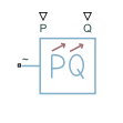
  • Dynamic Load (Three-Phase) block

Libraries:
Simscape / Electrical / Passive

Description

The Dynamic Load (Three-Phase) block models a balanced dynamic load for a balanced three-phase supply.

This table shows how the block calculates the consumed active and reactive power based on the voltage from the supply, V.

Range of V ValuesConsumed Active and Reactive Power
V>VminPactual=PinQactual=Qin
V<Vmin

The block models a load with an impedance equal to:

R=Vmin2PinPin2+Qin2X=Vmin2QinPin2+Qin2Z=R2+X2

In these equations:

  • Vmin is the value of the Minimum supply voltage (phase-to-phase RMS) parameter.

  • Pactual is the consumed active power of the Dynamic Load (Three-Phase) block.

  • Pin is the input active power of the Dynamic Load (Three-Phase) block, determined by external input port P.

  • Qactual is the consumed reactive power of the Dynamic Load (Three-Phase) block.

  • Qin is the input reactive power of the Dynamic Load (Three-Phase) block, determined by external input port Q.

The Dynamic Load (Three-Phase) block consumes or generates active power depending on the polarity of input active power Pin. If Pin > 0, the block consumes active power. If Pin < 0, the block generates active power.

Faults

To model a fault in the Dynamic Load (Three-Phase) block, in the Faults section, click the Add fault hyperlink in the parameter that corresponds to the specific fault that you want to model. When the Create Fault window opens, you use it to specify the fault properties. For more information about fault modeling, see Fault Behavior Modeling and Fault Triggering.

The Dynamic Load (Three-Phase) block allows you to model an electrical fault as an open circuit. The block can trigger fault events at a specific time.

Load-Flow Analysis

If the block is in a network that is compatible with the frequency-time simulation mode, you can perform a load-flow analysis on the network. A load-flow analysis provides steady-state values that you can use to initialize a machine.

For more information, see Perform a Load-Flow Analysis Using Simscape Electrical and Frequency and Time Simulation Mode.
Ports

Input

expand all

Physical signal port associated with real power, specified as a scalar.

Physical signal port associated with reactive power, specified as a scalar.

Conserving

expand all

Composite three-phase port associated with the three-phase voltage.

Dependencies

To enable this port, set Electrical connection to Composite three-phase ports.

Expanded three-phase port associated with the phase A voltage.

Dependencies

To enable this port, set Electrical connection to Expanded three-phase ports.

Expanded three-phase port associated with the phase B voltage.

Dependencies

To enable this port, set Electrical connection to Expanded three-phase ports.

Expanded three-phase port associated with the phase C voltage.

Dependencies

To enable this port, set Electrical connection to Expanded three-phase ports.

Parameters

expand all

Main

Whether to model composite or expanded three-phase ports.

When you select Composite three-phase ports, the ~ conserving port represents a composite three-phase port.

When you select Expanded three-phase ports, the a, b, and c conserving ports represent the individual phases of a three-phase system.

Since R2023a

Rated electrical frequency.

Minimum voltage, in phase-to-phase RMS, that the supply needs for the block to act as a dynamic load.

Since R2023a

Time constant associated with the transients of the terminal voltage measurement.

Since R2023a

Terminal voltage, in phase-to-phase RMS, at time zero.

Since R2023a

Terminal voltage angle of phase A at time zero.

Since R2023a

Parasitic conductance to electrical reference.

Faults

Option to add an open-circuit fault in the Dynamic Load (Three-Phase) block.

To add a fault, click the Add fault hyperlink.

Conductance during the open-circuit state.

Dependencies

To enable this parameter, add a fault to the Dynamic Load (Three-Phase) block by clicking the Add fault hyperlink in the Open circuit fault parameter.

After you create the fault, you can change the properties in the Fault Inspector window. When you open a block that has a fault, the Open Fault Inspector hyperlink appears instead of the Add fault hyperlink. For an example that shows how to include faults, see Analyze a DC Armature Winding Fault.

Simulation time at which the block enters the faulted state.

Dependencies

To enable this parameter, in the Fault Inspector window, set Trigger Type to Timed.

This parameter appears in the Trigger section of the Fault Inspector window. For more information, see Set Fault Triggers.

Extended Capabilities

C/C++ Code Generation
Generate C and C++ code using Simulink® Coder™.

Version History

Introduced in R2019a

expand all