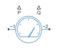
Power Sensor (Three-Phase)
Three-phase ideal active and reactive power sensor
Libraries:
Simscape /
Electrical /
Sensors & Transducers
Description
The Power Sensor (Three-Phase) block implements an ideal sensor for active and reactive power measurement in balanced or unbalanced three-phase branches.
For balanced branches, the block returns the correct value of the active and reactive power at all time instants. This is the preferred option for a load-flow analysis.
For unbalanced branches, the block independently measures the phasors of the three-phase voltages and currents by using a one-moving-period Fourier transform. The block then calculates the symmetrical set of positive-sequence, negative-sequence, and zero-sequence voltage and current phasors, and returns the value of the active and reactive power as the sum of their positive-sequence, negative-sequence, and zero-sequence components, respectively. (since R2026a)
For more information about how the block calculates the total active and reactive power, see the Equations section of Power Measurement (Three-Phase).
Load-Flow Analysis
If the block is in a network that is compatible with the frequency-time simulation mode, you can perform a load-flow analysis on the network. A load-flow analysis provides steady-state values that you can use to initialize a machine.
For more information, see Perform a Load-Flow Analysis Using Simscape Electrical and Frequency and Time Simulation Mode.
Ports
Conserving
Output
Parameters
References
[1] Willems, Jacques, "The IEEE standard 1459: What and why?", 2010 IEEE International Conference on Applied Measurements for Power Systems, Proceedings: 41-46.