Compare Fidelity Levels of Chopper Converters
This example shows how to use different levels of fidelity in chopper converters. You change the level of fidelity by changing the values for the Fidelity level, Switching device, and Integral protection diode parameters of the Four-Quadrant Chopper block. You also change the inputs to the G port. Using a higher level of fidelity improves the accuracy of the results but it also slows down simulation.
The system contains four four-quadrant choppers. The name of the Four-Quadrant Chopper block indicates the modeling approach:
Four-Quadrant Chopper ideal switches - To achieve a high level of accuracy, this model uses ideal switches and protection diodes at a 10 us sample time.
Four-Quadrant Chopper averaged switches averaged pulses - To yield accurate results even though you undersample the model at 50 us sample time, this model uses averaged switches with averaged pulses.
Four-Quadrant Chopper averaged switches duty cycles - To further increase the sample time and to operate as an ideal averaged converter, this model uses averaged switches and duty cycles instead of gate pulses.
Four-Quadrant Chopper equivalent model - To reduce simulation time even further, this model uses the equivalent model option which does not model the individual switching devices, but returns similar results to the implementation with ideal switches.
The Control subsystem contains a single-phase PWM waveform generator. The Scopes subsystem contains Scope blocks that allow you to see the simulation results.
Open Model

View Simulation Results from Simscape Logging
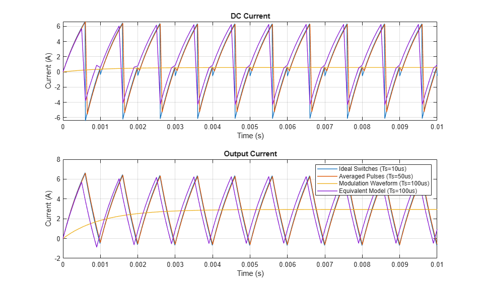
This plot compares the currents on both sides of the converter.
This plot compares the voltages on both sides of the converter.
