PWM Circuit Using 555 Timer
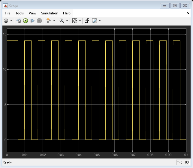
This example shows a pulse-width-modulated (PWM) output implemented using a 555 Timer in astable mode. The duty cycle is set by a potentiometer, P1. The potentiometer is controlled during run-time via Duty Cycle Control Knob. The scope shows the resultant output from the 555 Timer. To end the simulation, click on the Stop button.
Model

Simulation Results from Scopes
