Hardware Connections
C2000™ Microcontroller Blockset supports the following hardware configurations:
TI C2000 Hardware Connection
| TI C2000 Board | ||
|---|---|---|
LAUNCHXL or LaunchPad | LAUNCHXL-F28069M configuration | LAUNCHXL-F28069M/F28379D/F28027/F28027D/F280049C Configurations |
LAUNCHXL-F28379D configuration | ||
LAUNCHXL-F280049C configuration | ||
LAUNCHXL-F2827/F28027D configuration | ||
| controlCARD or Control card | F28069/F28035/F28335 control card configuration | F28069/F28035/F28335 Control Card Configuration |
F28M35x Concerto® and F28M36x Concerto control card configuration | ||
| TMDSRSLVR C2000 Resolver to Digital Conversion Kit | C2000 MCU Resolver Eval Kit [R2] | TMDSRSLVR C2000 Resolver to Digital Conversion Kit |
F28069/F28035/F28335 Control Card Configuration
The configuration includes the following hardware components:
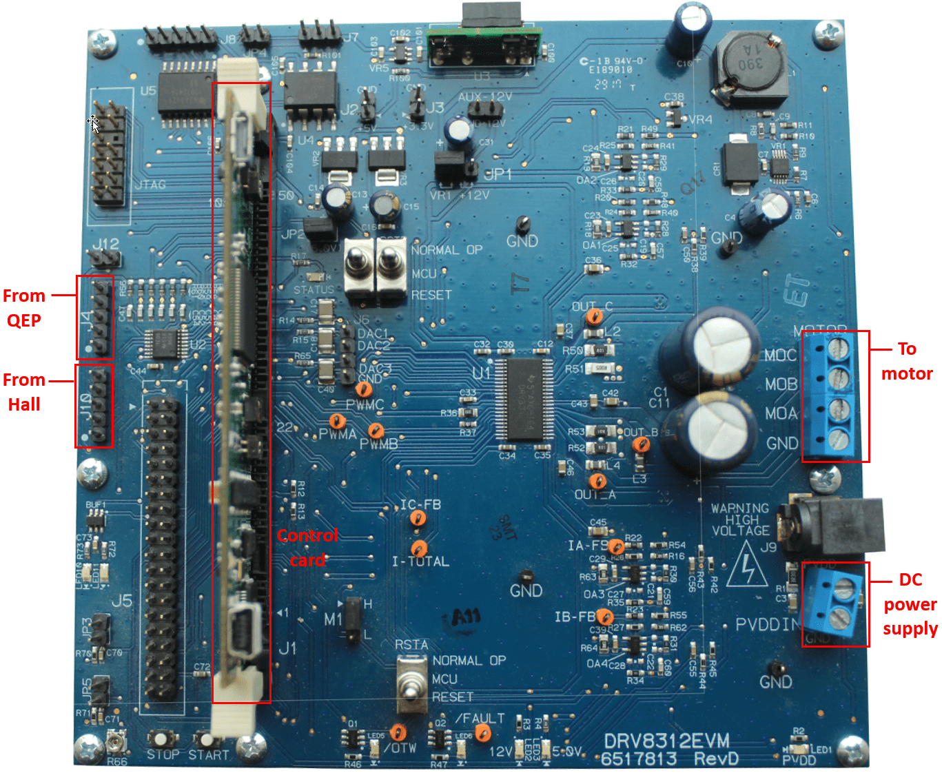
Texas Instruments® DRV8312-69M-KIT/DRV8312-C2-KIT inverter board
Texas Instruments F28069/F28035/F28335 microcontroller control card
Texas Instruments F28M35x Concerto/F28M36x Concerto microcontroller control card
Motor BLY171D (supports both Hall and quadrature encoder sensors)
Motor BLY172S (supports Hall sensor)
Quadrature encoder
DC power supply
Note
Due to auxiliary power supply related hardware issues, the DRV8312-69M-KIT/DRV8312-C2-KIT does not support the position sensors connected to some motors (for example, Teknic M-2310P motor).
The following steps describe the hardware connections for the F28069 control card configuration. You can use the same hardware connections for other control cards mentioned above.
Note
For F28M36x Concerto use TMSADAP180TO100 card to connect to DRV8312-C2-KIT.
Connect the F28069 (or any of the above mentioned) control card to J1 of DRV8312-69M-KIT inverter board.
Connect the motor three phases, to MOA, MOB, and MOC on the inverter board.
Connect the DC power supply (24V) to PVDDIN on the inverter board.
Warning
Be careful when connecting PVDD and GND to the positive and negative connections of the DC power supply. A reverse connection can damage the hardware components.
The following step describes about interfacing the quadrature encoder sensor:
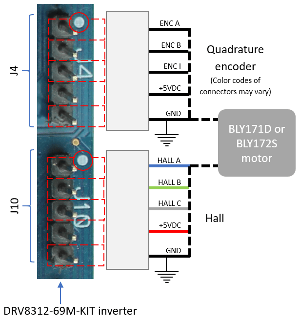
Connect the quadrature encoder pins (G, I, A, 5V, B) to J4 on the inverter board.
To implement position-sensing by using Hall sensor, use a motor that has inbuilt Hall sensors (for example, BLY171D and BLY172S). The following steps describe the steps to interface the Hall sensor:
Connect the Hall sensor encoder output to J10 on the inverter board.
We recommend the following jumper settings for DRV8312-69M-KIT/DRV8312-C2-KIT inverter board when working with C2000 Microcontroller Blockset. You can customize these settings depending on the application requirements. For more information about these settings, see the device user guide available on Texas Instruments website.
JP1 – VR1
JP2 – ON
JP3 – OFF
JP4 – OFF
JP5 – OFF
M1 – H
J2 – OFF
J3 – OFF
RSTA – MCU
RSTB - MCU
RSTC - MCU
LAUNCHXL-F28069M/F28379D/F28027/F28027D/F280049C Configurations
The LAUNCHXL-F28069M configuration includes the following hardware components:
LAUNCHXL-F28069M controller
BOOSTXL-DRV8305 (supported inverter)
Teknic motor M-2310P (supports both Hall and quadrature encoder sensors)
Motor BLY171D (supports both Hall and quadrature encoder sensors)
Motor BLY172S (supports Hall sensor)
DC power supply
The LAUNCHXL-F28379D configuration includes the following hardware components:
LAUNCHXL-F28379D controller
BOOSTXL-DRV8305 and BOOSTXL-3PHGANINV (supported inverters)
Teknic motor M-2310P (supports both Hall and quadrature encoder sensors)
Motor BLY171D (supports both Hall and quadrature encoder sensors)
Motor BLY172S (supports Hall sensor)
DC power supply
The LAUNCHXL-F28027/F28027D/F280049C configuration includes the following hardware components:
LAUNCHXL-F28027 controller
LAUNCHXL-F280049 controller
BOOSTXL-DRV8305
Teknic motor M-2310P
Motor BLY171D
Motor BLY172S
DC power supply
Note
LAUNCHXL-F28027/F28027D controller is sensorless and does not support both Hall and quadrature encoder sensors.
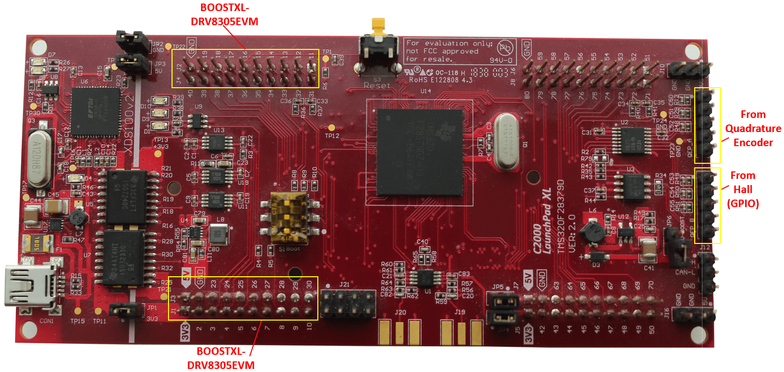
The following steps describe the hardware connections for the LAUNCHXL-F28069M, LAUNCHXL-F28379D, LAUNCHXL-F28027D, and LAUNCHXL-F280049C configurations:
Attach the BOOSTXL inverter board to J1, J2, J3, J4 on the LAUNCHXL-F28069M or F28379D or F280049C and J1, J2, J5, J6 for LAUNCHXL -F28027/27F.
Note
Attach the inverter board to the controller board such that J1, J2 of BOOSTXL aligns with J1, J2 of LAUNCHXL.
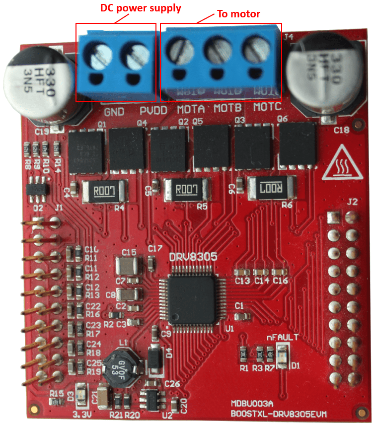
Connect the motor three phases, to MOTA, MOTB, and MOTC on the BOOSTXL inverter board.
Connect the DC power supply (24V) to PVDD and GND on the BOOSTXL inverter board.
Warning
Be careful when connecting PVDD and GND to the positive and negative connections of the DC power supply. A reverse connection can damage the hardware components.

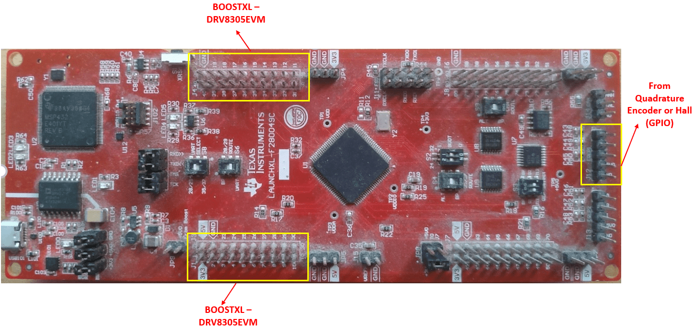
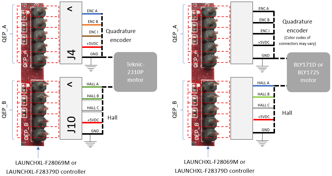
The following step describes about interfacing the quadrature encoder sensor:
Connect the quadrature encoder pins (G, I, A, 5V, B) to QEP_A on the LAUNCHXL- F28379D/F28069M controller board or EQEP1 (J12) of the LAUNCHXL-F280049C.
To implement position-sensing by using Hall sensor, use a motor that has inbuilt Hall sensors (for example, Teknic motor M-2310P, BLY171D and BLY172S). The following steps describe the steps to interface the Hall sensor:
Connect the Hall sensor encoder output to a GPIO port that is configured as eCAP, on the LAUNCHXL controller board (QEP_B for LAUNCHXL-F28379D, EQEP1 (J12) for LAUNCHXL-F280049C).
We recommend the following jumper settings for the LAUNCHXL inverter boards when working with Motor Control Blockset™. You can customize these settings depending on the application requirements. For more information about these settings, see the device user guide available on Texas Instruments website.
For LAUNCHXL-F28069M controller
JP1 – ON
JP2 – ON
JP3 – ON
JP4 – ON
JP5 – ON
JP6 – OFF
JP7 – ON
For LAUNCHXL-F28379D controller
JP1 – ON
JP2 – ON
JP3 – ON
JP4 – ON
JP5 – ON
JP6 – OFF
For LAUNCHXL-F28027 controller
S4 – ON
For LAUNCHXL-F280049C controller
S8 – 0, S6 – 0 : Required for serial communication.
For QEP1, S3 position 2 : down, S4 – UP (1)
For QEP2, S3 position 1 : down
JP1, JP2, JP3, JP8: ON
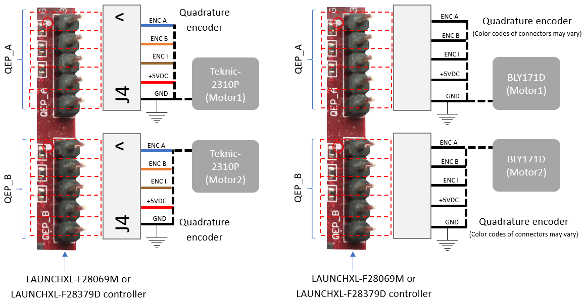
Instructions for Dyno (Dual Motor) Setup
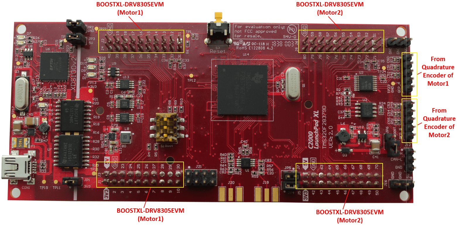
Connect the three phases of Motor1 and Motor2, to MOTA, MOTB, and MOTC on the corresponding BOOSTXL inverter boards.
Attach the BOOSTXL inverter board (connected to Motor1) to J1, J2, J3, J4 on the LAUNCHXL controller board.
Note
Attach the inverter board to the controller board such that J1, J2 of BOOSTXL aligns with J1, J2 of LAUNCHXL.
Attach the BOOSTXL inverter board (connected to Motor2) to J5, J6, J7, J8 on the LAUNCHXL controller board.
Note
Attach the inverter board to the controller board such that J1, J2 of BOOSTXL aligns with J5, J6 of LAUNCHXL.
Connect the DC power supply (24V) to PVDD and GND on both BOOSTXL inverter boards.
Note
Connect the PVDD and GND on the BOOSTXL boards (for MOTOR1 and MOTOR2) to the same power supply. When one motor consumes power, the second motor generates power. If you connect both motors to the same power supply, the power generated by one motor is consumed by the other motor. The DC power supply delivers power only for the losses.
Connect the quadrature encoder pins of Motor1 (G, I, A, 5V, B) to QEP_A on the LAUNCHXL controller board.
Connect the quadrature encoder pins of Motor2 (G, I, A, 5V, B) to QEP_B on the LAUNCHXL controller board.
Warning
Be careful when connecting PVDD and GND to the positive and negative connections of the DC power supply. A reverse connection can damage the hardware components.
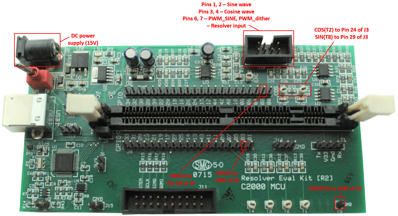
TMDSRSLVR C2000 Resolver to Digital Conversion Kit
The TMDSRSLVR C2000 Resolver to Digital Conversion Kit configuration includes the following hardware components:
LAUNCHXL-F28069M controller
BOOSTXL-DRV8305 (supported inverter)
DC power supply
TMDSRSLVR C2000 Resolver to Digital Conversion Kit (Resolver Eval Kit [R2])
Resolver encoder
The following steps describe the hardware connections for the TMDSRSLVR board:
Connect DC power supply (15V) to J2 on the TMDSRSLVR board.
Connect the resolver output pins for sine wave to pins 1, 2 of J10 on the TMDSRSLVR board.
Connect the resolver output pins for cosine wave to pins 3, 4 of J10 on the TMDSRSLVR board.
Connect the resolver input pins to the PWM_dither and PWM_SINE pins of J10 on the TMDSRSLVR board.
The following step describes the hardware connection for the LAUNCHXL-F28069M controller board:
Connect the LAUNCHXL-F28069M controller board to a computer via USB port.
The following steps describe the hardware connections between the MCU Resolver Eval Kit [R2] and LAUNCHXL-F28069M controller boards:
Connect the COS(T2) pin on the TMDSRSLVR board to pin 24 of J3 on the LAUNCHXL-F28069M controller board.
Connect the SIN(T8) pin on the TMDSRSLVR board to pin 29 of J3 on the LAUNCHXL-F28069M controller board.
Connect the GPIO2 pin on the TMDSRSLVR board to pin 38 of J4 on the LAUNCHXL-F28069M controller board.