Main Content

Solid Axle Suspension - Mapped

Mapped solid axle suspension

  • Solid Axle Suspension - Mapped block

Libraries:
Vehicle Dynamics Blockset / Suspension

Description

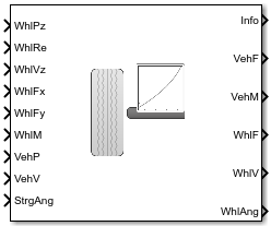
The Solid Axle Suspension - Mapped block implements a mapped solid axle suspension for multiple axles with multiple wheels per axle.

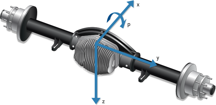
The block models the suspension compliance, damping, and geometric effects as functions of the wheel positions and velocities, with axle-specific compliance and damping parameters. Using the wheel position and velocity, the block calculates the vertical wheel position and suspension forces on the vehicle and wheel. The block uses the Z-down coordinate system (defined in SAE J670) and a solid axle coordinate system. The solid axle coordinate system is aligned with the Z-down vehicle coordinate system, with the x-axis in the direction of forward vehicle motion.

Illustration of a solid axle

This table describes the settings you can specify for each suspension element.

Suspension ElementSetting

Axle

  • Multiple wheels

  • Suspension parameters

Wheel

  • Steering angles

The block contains energy-storing spring elements and energy-dissipating damper elements. The block also stores energy via the axle roll angular acceleration and axle center of mass vertical and lateral acceleration.

This table summarizes the block parameter settings for a vehicle with:

  • Two axles

  • Two wheels per axle

  • Steering angle input for both wheels on the front axle

ParameterSetting
Number of axles, NumAxl

2

Number of wheels by axle, NumWhlsByAxl

[2 2]

Steered axle enable by axle, StrgEnByAxl

[1 0]

The block uses the wheel number, t, to index the input and output signals. This table summarizes the wheel, axle, and corresponding wheel number for a vehicle with:

  • Two axles

  • Two wheels per axle

WheelAxleWheel Number
Front leftFront1
Front rightFront2
Rear leftRear1
Rear rightRear2

Suspension Compliance and Damping

The block uses a lookup table that relates the vertical damping and compliance to the suspension height, suspension height rate of change, and steering angle. You can calibrate the wheel force lookup table so that steering angle changes from the nominal center position generate a force that increases the vehicle height. Specifically, the block:

Uses

To Calculate

  • Longitudinal and lateral displacement and velocity of the vehicle.

  • Longitudinal and lateral displacement and velocity of the wheel.

  • Vertical wheel forces applied to the vehicle.

  • Suspension forces applied to the axle center.

  • Vertical displacements and velocities of the vehicle and wheel.

  • Longitudinal, lateral, and vertical suspension forces and moments applied to the vehicle.

  • Longitudinal, lateral, and vertical suspension forces and moments applied to the wheel.

To calculate the dynamics of the axle, the block implements these equations. The block neglects the effects of:

  • Lateral and longitudinal translational velocity.

  • Angular velocity about the vertical and lateral axes.

[x¨ay¨az¨a]=1Ma[FxaFyaFza]+[x˙ay˙az˙a]×[pqr]=1Ma[00Fza]+[00z˙a]×[p00]+[00g]=[0pz˙aFzaMa+g][p˙q˙r˙]=[[MxMyMz][pqr]×[Ixx000Iyy000Izz][pqr]][Ixx000Iyy000Izz]1=[[Mx00][pq0]×[Ixx000Iyy000Izz][p00]][Ixx000Iyy000Izz]1=[MxIxx00]

For the forces and moments, the block uses lookup tables.

Fwza,t=f(zva,tzwa,t,z˙va,tz˙wa,t,δsteera,t)Mvza,t=f(zva,tzwa,t,z˙va,tz˙wa,t,δsteera,t)

The suspension forces and moments applied to the vehicle are equal to the suspension forces and moments applied to the wheel.

Fvxa,t=Fwxa,tFvya,t=Fwya,tFvza,t=Fwza,tMvxa,t=Mwxa,t+Fwya,t(Rewya,t+Ha,t)Mvya,t=Mwya,t+Fwxa,t(Rewxa,t+Ha,t)Mvza,t=Mwza,t

The equations use these variables.

Fwza,t, Mwza,t

Suspension force and moment applied to the wheel on axle a, wheel t along wheel-fixed z-axis

Fwxa,t, Mwxa,t

Suspension force and moment applied to the wheel on axle a, wheel t along wheel-fixed x-axis

Fwya,t, Mwya,t

Suspension force and moment applied to the wheel on axle a, wheel t along wheel-fixed y-axis

Fvza,t, Mvza,t

Suspension force and moment applied to the vehicle on axle a, wheel t along wheel-fixed z-axis

Fvxa,t, Mvxa,t

Suspension force and moment applied to the vehicle on axle a, wheel t along wheel-fixed x-axis

Fvya,t, Mvya,t

Suspension force and moment applied to the vehicle on axle a, wheel t along wheel-fixed y-axis

Fz0a

Vertical suspension spring preload force applied to the wheels on axle a

kza

Vertical spring constant applied to wheels on axle a

kwazWheel and axle interface compliance constant
mhsteera

Steering angle to vertical force slope applied at wheel carrier for wheels on axle a

δsteera,t

Steering angle input for axle a, wheel t

cza

Vertical damping constant applied to wheels on axle a

cwazWheel and axle interface damping constant
Rewa,t

Effective wheel radius for axle a, wheel t

Fzhstopa,t

Vertical hardstop force at axle a, wheel t, along the vehicle-fixed z-axis

Fzaswya,t

Vertical anti-sway force at axle a, wheel t, along the vehicle-fixed z-axis

Fwaz0Wheel and axle interface compliance constant
zva,t, żva,t

Vehicle displacement and velocity at axle a, wheel t, along the vehicle-fixed z-axis

zwa,t, żwa,t

Wheel displacement and velocity at axle a, wheel t, along the vehicle-fixed z-axis

xva,t, va,t

Vehicle displacement and velocity at axle a, wheel t, along the vehicle-fixed z-axis

xwa,t, wa,t

Wheel displacement and velocity at axle a, wheel t, along the vehicle-fixed z-axis

yva,t, va,t

Vehicle displacement and velocity at axle a, wheel t, along the vehicle-fixed y-axis

ywa,t, wa,t

Wheel displacement and velocity at axle a, wheel t, along the vehicle-fixed y-axis

Ha,t

Suspension height at axle a, wheel t

Rewa,tEffective wheel radius at axle a, wheel t

Camber, Caster, and Toe Angles

To calculate the camber, caster, and toe angles, the block uses a lookup table, Galookup, that is a function of the suspension height and steering angle.

[ξa,tηa,tζa,t]=Galookupf(zwa,tzva,t,δsteera,t)

The equations use these variables.

ξa,t

Camber angle of wheel on axle a, wheel t

ηa,t

Caster angle of wheel on axle a, wheel t

ζa,t

Toe angle of wheel on axle a, wheel t

δsteera,t

Steering angle input for axle a, wheel t

zva,t

Vehicle displacement at axle a, wheel t, along vehicle-fixed z-axis

zwa,t

Wheel displacement at axle a, wheel t, along vehicle-fixed z-axis

Steering Angles

Optionally, you can input steering angles for the wheels. To calculate the steering angles for the wheels, the block offsets the input steering angles as a function of the suspension height. For the calculation, the block uses a lookup table, Galookup, that is a function of the suspension position and steering angle.

δwhlsteera,t=δsteera,t+Galookupf(zwa,tzva,t,δsteera,t)

The equation uses these variables.

δwhlsteera,t

Wheel steering angle for axle a, wheel t

δsteera,t

Steering angle input for axle a, wheel t

zva,t

Vehicle displacement at axle a, wheel t, along the vehicle-fixed z-axis

zwa,t

Wheel displacement at axle a, wheel t, along the vehicle-fixed z-axis

Power and Energy

The block calculates these suspension characteristics for each axle, a, and wheel, t.

CalculationEquation

Dissipated power, Psuspa,t

Psuspa,t=Fwzlookupa(z˙va,tz˙wa,t,z˙va,tz˙wa,t,δsteera,t)

Absorbed energy, Esuspa,t

Esuspa,t=Fwzlookupa(z˙va,tz˙wa,t,z˙va,tz˙wa,t,δsteera,t)

Suspension height, Ha,t

Ha,t=(zva,tzwa,tmedian(f_susp_dz_bp))

Distance from wheel carrier center to tire/road interface

zwtra,t=Rewa,t+Ha,t

The equations use these variables.

mhsteera

Steering angle to vertical force slope applied at wheel carrier for wheels on axle a

δsteera,t

Steering angle input for axle a, wheel t

Rewa,t

Axle a, wheel t effective wheel radius from wheel carrier center to tire/road interface

f_susp_dz_bp

Vertical axis suspension height breakpoints

zwtra,t

Distance from wheel carrier center to tire/road interface, along the vehicle-fixed z-axis

zva,t, żva,t

Vehicle displacement and velocity at axle a, wheel t, along the vehicle-fixed z-axis

zwa,t, żwa,t

Wheel displacement and velocity at axle a, wheel t, along the vehicle-fixed z-axis

Ports

Input

expand all

Wheel displacement, zw, along wheel-fixed z-axis, in m. Array dimensions are 1 by the total number of wheels on the vehicle.

For example, for a two-axle vehicle with two wheels per axle, the WhlPz:

  • Signal array dimensions are [1x4].

    WhlPz=zw=[zw1,1zw1,2zw2,1zw2,2]

    WheelArray ElementAxleWheel Number
    Front leftWhlPz(1,1)11
    Front rightWhlPz(1,2)12
    Rear leftWhlPz(1,3)21
    Rear rightWhlPz(1,4)22

Effective wheel radius, Rew, in m. Array dimensions are 1 by the total number of wheels on the vehicle.

For example, for a two-axle vehicle with two wheels per axle, the WhlRe:

  • Signal array dimensions are [1x4].

    WhlRe=Rew=[Rew1,1Rew1,2Rew2,1Rew2,2]

    WheelArray ElementAxleWheel Number
    Front leftWhlRe(1,1)11
    Front rightWhlRe(1,2)12
    Rear leftWhlRe(1,3)21
    Rear rightWhlRe(1,4)22

Wheel velocity, żw, along wheel-fixed z-axis, in m. Array dimensions are 1 by the total number of wheels on the vehicle.

For example, for a two-axle vehicle with two wheels per axle, the WhlVz:

  • Signal array dimensions are [1x4].

    WhlVz=z˙w=[z˙w1,1z˙w1,2z˙w2,1z˙w2,2]

    WheelArray ElementAxleWheel Number
    Front leftWhlVz(1,1)11
    Front rightWhlVz(1,2)12
    Rear leftWhlVz(1,3)21
    Rear rightWhlVz(1,4)22

Longitudinal wheel force applied to vehicle, Fwx, along the vehicle-fixed x-axis. Array dimensions are 1 by the total number of wheels on the vehicle.

For example, for a two-axle vehicle with two wheels per axle, the WhlFx:

  • Signal array dimensions are [1x4].

    WhlFx=Fwx=[Fwx1,1Fwx1,2Fwx2,1Fwx2,2]

    WheelArray ElementAxleWheel Number
    Front leftWhlFx(1,1)11
    Front rightWhlFx(1,2)12
    Rear leftWhlFx(1,3)21
    Rear rightWhlFx(1,4)22

Lateral wheel force applied to vehicle, Fwy, along the vehicle-fixed y-axis. Array dimensions are 1 by the total number of wheels on the vehicle.

For example, for a two-axle vehicle with two wheels per axle, the WhlFy:

  • Signal array dimensions are [1x4].

    WhlFy=Fwy=[Fwy1,1Fwy1,2Fwy2,1Fwy2,2]

    WheelArray ElementAxleWheel Number
    Front leftWhlFy(1,1)11
    Front rightWhlFy(1,2)12
    Rear leftWhlFy(1.3)21
    Rear rightWhlFy(1,4)22

Longitudinal, lateral, and vertical suspension moments at axle a, wheel t, applied to the wheel at the axle wheel carrier reference coordinate, in N·m. Input array dimensions are 3 by the number of wheels on the vehicle.

  • WhlM(1,...) — Suspension moment applied to the wheel about the vehicle-fixed x-axis (longitudinal)

  • WhlM(2,...) — Suspension moment applied to the wheel about the vehicle-fixed y-axis (lateral)

  • WhlM(3,...) — Suspension moment applied to the wheel about the vehicle-fixed z-axis (vertical)

For example, for a two-axle vehicle with two wheels per axle, the WhlM:

  • Signal dimensions are [3x4].

  • Signal contains suspension moments applied to four wheels according to their axle and wheel locations.

    WhlM=Mw=[Mwx1,1Mwx1,2Mwx2,1Mwx2,2Mwy1,1Mwy1,2Mwy2,1Mwy2,2Mwz1,1Mwz1,2Mwz2,1Mwz2,2]

    WheelArray ElementAxleWheel NumberMoment Axis
    Front leftWhlM(1,1)11Vehicle-fixed x-axis (longitudinal)
    Front rightWhlM(1,2)12
    Rear leftWhlM(1,3)21
    Rear rightWhlM(1,4)22
    Front leftWhlM(2,1)11Vehicle-fixed y-axis (lateral)
    Front rightWhlM(2,2)12
    Rear leftWhlM(2,3)21
    Rear rightWhlM(2,4)22
    Front leftWhlM(3,1)11Vehicle-fixed z-axis (vertical)
    Front rightWhlM(3,2)12
    Rear leftWhlM(3,3)21
    Rear rightWhlM(3,4)22

Vehicle displacement from axle a, wheel t along vehicle-fixed coordinate system, in m. Input array dimensions are 3 by the number of wheels on the vehicle.

  • VehP(1,...) — Vehicle displacement from wheel, xv, along the vehicle-fixed x-axis

  • VehP(2,...) — Vehicle displacement from wheel, yv, along the vehicle-fixed y-axis

  • VehP(3,...) — Vehicle displacement from wheel, zv, along the vehicle-fixed z-axis

For example, for a two-axle vehicle with two wheels per axle, the VehP:

  • Signal dimensions are [3x4].

  • Signal contains four displacements according to their axle and wheel locations.

    VehP=[xvyvzv]=[xv1,1xv1,2xv2,1xv2,2yv1,1yv1,2yv2,1yv2,2zv1,1zv1,2zv2,1zv2,2]

    WheelArray ElementAxleWheel NumberAxis
    Front leftVehP(1,1)11Vehicle-fixed x-axis
    Front rightVehP(1,2)12
    Rear leftVehP(1,3)21
    Rear rightVehP(1,4)22
    Front leftVehP(2,1)11Vehicle-fixed y-axis
    Front rightVehP(2,2)12
    Rear leftVehP(2,3)21
    Rear rightVehP(2,4)22
    Front leftVehP(3,1)11Vehicle-fixed z-axis
    Front rightVehP(3,2)12
    Rear leftVehP(3,3)21
    Rear rightVehP(3,4)22

Vehicle velocity at axle a, wheel t along vehicle-fixed coordinate system, in m. Input array dimensions are 3 by the number of wheels on the vehicle.

  • VehV(1,...) — Vehicle velocity at wheel, xv, along the vehicle-fixed x-axis

  • VehV(2,...) — Vehicle velocity at wheel, yv, along the vehicle-fixed y-axis

  • VehV(3,...) — Vehicle velocity at wheel, zv, along the vehicle-fixed z-axis

For example, for a two-axle vehicle with two wheels per axle, the VehV:

  • Signal dimensions are [3x4].

  • Signal contains 4 velocities according to their axle and wheel locations.

    VehV=[x˙vy˙vz˙v]=[x˙v1,1x˙v1,2x˙v2,1x˙v2,2y˙v1,1y˙v1,2y˙v2,1y˙v2,2z˙v1,1z˙v1,2z˙v2,1z˙v2,2]

    WheelArray ElementAxleWheel NumberAxis
    Front leftVehV(1,1)11Vehicle-fixed x-axis
    Front rightVehV(1,2)12
    Rear leftVehV(1,3)21
    Rear rightVehV(1,4)22
    Front leftVehV(2,1)11Vehicle-fixed y-axis
    Front rightVehV(2,2)12
    Rear leftVehV(2,3)21
    Rear rightVehV(2,4)22
    Front leftVehV(3,1)11Vehicle-fixed z-axis
    Front rightVehV(3,2)12
    Rear leftVehV(3,3)21
    Rear rightVehV(3,4)22

Optional steering angle for each wheel, δ. Input array dimensions are 1 by the number of steered wheels.

For example, for a two-axle vehicle with two wheels per axle, you can input steering angles for both wheels on the first axle.

  • To enable the StrgAng port, set Steered axle enable by axle, StrgEnByAxl to [1 0]. The input signal array dimensions are [1x2].

  • The StrgAng signal contains two steering angles according to their axle and wheel locations.

    StrgAng=δsteer=[δsteer1,1δsteer1,2]

    WheelArray ElementAxleWheel Number
    Front leftStrgAng(1,1)11
    Front rightStrgAng(1,2)12

Dependencies

To enable the port StrgAng, set an element of the Steered axle enable by axle, StrgEnByAxl vector to 1.

Output

expand all

Bus signal containing block values. The signals are arrays that depend on the wheel location.

For example, these are the indices for a two-axle, two-wheel vehicle. The total number of wheels is four.

  • 1D array signal (1-by-4)

    Array ElementAxleWheel Number
    (1,1)11
    (1,2)12
    (1,3)21
    (1,4)22

  • 3D array signal (3-by-4)

    Array ElementAxleWheel Number
    (1,1)11
    (1,2)12
    (1,3)21
    (1,4)22
    (2,1)11
    (2,2)12
    (2,3)21
    (2,4)22
    (3,1)11
    (3,2)12
    (3,3)21
    (3,4)22

SignalDescriptionArray SignalVariableUnits
Camber

Wheel angles according to the axle.

1D

WhlAng[1,...]=ξ=[ξa,t]

rad

Caster

WhlAng[2,...]=η=[ηa,t]

Toe

WhlAng[3,...]=ζ=[ζa,t]

Height

Suspension height

1D

H

m

Power

Suspension power dissipation

1D

Psusp

W

Energy

Suspension absorbed energy

1D

Esusp

J

VehF

Suspension forces applied to the vehicle

3D

For a two-axle, two wheels per axle vehicle:

VehF=Fv=[Fvx1,1Fvx1,2Fvx2,1Fvx2,2Fvy1,1Fvy1,2Fvy2,1Fvy2,2Fvz1,1Fvz1,2Fvz2,1Fvz2,2]

N

VehM

Suspension moments applied to vehicle

3D

For a two-axle, two wheels per axle vehicle:

VehM=Mv=[Mvx1,1Mvx1,2Mvx2,1Mvx2,2Mvy1,1Mvy1,2Mvy2,1Mvy2,2Mvz1,1Mvz1,2Mvz2,1Mvz2,2]

N·m

WhlF

Suspension force applied to wheel

3D

For a two-axle, two wheels per axle vehicle:

WhlF=Fw=[Fwx1,1Fwx1,2Fwx2,1Fwx2,2Fwy1,1Fwy1,2Fwy2,1Fwy2,2Fwz1,1Fwz1,2Fwz2,1Fwz2,2]

N

WhlP

Wheel displacement

3D

For a two-axle, two wheels per axle vehicle:

WhlP=[xwywzw]=[xw1,1xw1,2xw2,1xw2,2yw1,1yw1,2yw2,1ywy2,2zwtr1,1zwtr1,2zwtr2,1zwtr2,2]

m

WhlV

Wheel velocity

3D

For a two-axle, two wheels per axle vehicle:

WhlV=[x˙wy˙wz˙w]=[x˙w1,1x˙w1,2x˙w2,1x˙w2,2y˙w1,1y˙w1,2y˙w2,1y˙w2,2z˙w1,1z˙w1,2z˙w2,1z˙w2,2]

m/s

WhlAng

Wheel camber, caster, toe angles

3D

For a two-axle, two wheels per axle vehicle:

WhlAng=[ξηζ]=[ξ1,1ξ1,2ξ2,1ξ2,2η1,1η1,2η2,1η2,2ζ1,1ζ1,2ζ2,1ζ2,2]

rad

Longitudinal, lateral, and vertical suspension force at axle a, wheel t, applied to the vehicle at the suspension connection point, in N. Array dimensions are 3 by the number of wheels on the vehicle.

  • VehF(1,...) — Suspension force applied to vehicle along the vehicle-fixed x-axis (longitudinal)

  • VehF(2,...) — Suspension force applied to vehicle along the vehicle-fixed y-axis (lateral)

  • VehF(3,...) — Suspension force applied to vehicle along the vehicle-fixed z-axis (vertical)

For example, for a two-axle vehicle with two wheels per axle, the VehF:

  • Signal dimensions are [3x4].

  • Signal contains suspension forces applied to the vehicle according to the axle and wheel locations.

    VehF=Fv=[Fvx1,1Fvx1,2Fvx2,1Fvx2,2Fvy1,1Fvy1,2Fvy2,1Fvy2,2Fvz1,1Fvz1,2Fvz2,1Fvz2,2]

    WheelArray ElementAxleWheel NumberForce Axis
    Front leftVehF(1,1)11Vehicle-fixed x-axis (longitudinal)
    Front rightVehF(1,2)12
    Rear leftVehF(1,3)21
    Rear rightVehF(1,4)22
    Front leftVehF(2,1)11Vehicle-fixed y-axis (lateral)
    Front rightVehF(2,2)12
    Rear leftVehF(2,3)21
    Rear rightVehF(2,4)22
    Front leftVehF(3,1)11Vehicle-fixed z-axis (vertical)
    Front rightVehF(3,2)12
    Rear leftVehF(3,3)21
    Rear rightVehF(3,4)22

Longitudinal, lateral, and vertical suspension moment at axle a, wheel t, applied to the vehicle at the suspension connection point, in N·m. Array dimensions are 3 by the number of wheels on the vehicle.

  • VehM(1,...) — Suspension moment applied to the vehicle about the vehicle-fixed x-axis (longitudinal)

  • VehM(2,...) — Suspension moment applied to the vehicle about the vehicle-fixed y-axis (lateral)

  • VehM(3,...) — Suspension moment applied to the vehicle about the vehicle-fixed z-axis (vertical)

For example, for a two-axle vehicle with two wheels per axle, the VehM:

  • Signal dimensions are [3x4].

  • Signal contains suspension moments applied to vehicle according to the axle and wheel locations.

    VehM=Mv=[Mvx1,1Mvx1,2Mvx2,1Mvx2,2Mvy1,1Mvy1,2Mvy2,1Mvy2,2Mvz1,1Mvz1,2Mvz2,1Mvz2,2]

    Array ElementAxleWheel NumberMoment Axis
    VehM(1,1)11Vehicle-fixed x-axis (longitudinal)
    VehM(1,2)12
    VehM(1,3)21
    VehM(1,4)22
    VehM(2,1)11Vehicle-fixed y-axis (lateral)
    VehM(2,2)12
    VehM(2,3)21
    VehM(2,4)22
    VehM(3,1)11Vehicle-fixed z-axis (vertical)
    VehM(3,2)12
    VehM(3,3)21
    VehM(3,4)22

Longitudinal, lateral, and vertical suspension forces at axle a, wheel t, applied to the wheel at the axle wheel carrier reference coordinate, in N. Array dimensions are 3 by the number of wheels on the vehicle.

  • WhlF(1,...) — Suspension force on wheel along the vehicle-fixed x-axis (longitudinal)

  • WhlF(2,...) — Suspension force on wheel along the vehicle-fixed y-axis (lateral)

  • WhlF(3,...) — Suspension force on wheel along the vehicle-fixed z-axis (vertical)

For example, for a two-axle vehicle with two wheels per axle, the WhlF:

  • Signal dimensions are [3x4].

  • Signal contains wheel forces applied to the vehicle according to the axle and wheel locations.

    WhlF=Fw=[Fwx1,1Fwx1,2Fwx2,1Fwx2,2Fwy1,1Fwy1,2Fwy2,1Fwy2,2Fwz1,1Fwz1,2Fwz2,1Fwz2,2]

    WheelArray ElementAxleWheel NumberForce Axis
    Front leftWhlF(1,1)11Vehicle-fixed x-axis (longitudinal)
    Front rightWhlF(1,2)12
    Rear leftWhlF(1,3)21
    Rear rightWhlF(1,4)22
    Front leftWhlF(2,1)11Vehicle-fixed y-axis (lateral)
    Front rightWhlF(2,2)12
    Rear leftWhlF(2,3)21
    Rear rightWhlF(2,4)22
    Front leftWhlF(3,1)11Vehicle-fixed z-axis (vertical)
    Front rightWhlF(3,2)12
    Rear leftWhlF(3,3)21
    Rear rightWhlF(3,4)22

Longitudinal, lateral, and vertical wheel velocity at axle a, wheel t, in m/s. Array dimensions are 3 by the number of wheels on the vehicle.

  • WhlV(1,...) — Wheel velocity along the vehicle-fixed x-axis (longitudinal)

  • WhlV(2,...) — Wheel velocity along the vehicle-fixed y-axis (lateral)

  • WhlV(3,...) — Wheel velocity along the vehicle-fixed z-axis (vertical)

For example, for a two-axle vehicle with two wheels per axle, the WhlV:

  • Signal dimensions are [3x4].

  • Signal contains wheel forces applied to the vehicle according to the axle and wheel locations.

    WhlV=[x˙wy˙wz˙w]=[x˙w1,1x˙w1,2x˙w2,1x˙w2,2y˙w1,1y˙w1,2y˙w2,1y˙w2,2z˙w1,1z˙w1,2z˙w2,1z˙w2,2]

    WheelArray ElementAxleWheel NumberForce Axis
    Front leftWhlV(1,1)11Vehicle-fixed x-axis (longitudinal)
    Front rightWhlV(1,2)12
    Rear leftWhlV(1,3)21
    Rear rightWhlV(1,4)22
    Front leftWhlV(2,1)11Vehicle-fixed y-axis (lateral)
    Front rightWhlV(2,2)12
    Rear leftWhlV(2,3)21
    Rear rightWhlV(2,4)22
    Front leftWhlV(3,1)11Vehicle-fixed z-axis (vertical)
    Front rightWhlV(3,2)12
    Rear leftWhlV(3,3)21
    Rear rightWhlV(3,4)22

Camber, caster, and toe angles at axle a, wheel t, in rad. Array dimensions are 3 by the number of wheels on the vehicle.

  • WhlAng(1,...) — Camber angle

  • WhlAng(2,...) — Caster angle

  • WhlAng(3,...) — Toe angle

For example, for a two-axle vehicle with two wheels per axle, the WhlAng:

  • Signal dimensions are [3x4].

  • Signal contains angles according to the axle and wheel locations.

    WhlAng=[ξηζ]=[ξ1,1ξ1,2ξ2,1ξ2,2η1,1η1,2η2,1η2,2ζ1,1ζ1,2ζ2,1ζ2,2]

    WheelArray ElementAxleWheel NumberAngle
    Front leftWhlAng(1,1)11

    Camber

    Front rightWhlAng(1,2)12
    Rear leftWhlAng(1,3)21
    Rear rightWhlAng(1,4)22
    Front leftWhlAng(2,1)11

    Caster

    Front rightWhlAng(2,2)12
    Rear leftWhlAng(2,3)21
    Rear rightWhlAng(2,4)22
    Front leftWhlAng(3,1)11

    Toe

    Front rightWhlF(3,2)12
    Rear leftWhlF(3,3)21
    Rear rightWhlF(3,4)22

Parameters

expand all

Axles

Number of axles, Na, dimensionless.

Number of wheels per axle, Nta, dimensionless. Vector is 1 by the number of vehicle axles, Na. For example, [1,2] represents one wheel on axle one and two wheels on axle two.

Boolean vector that enables axle steering, Ensteer, dimensionless. Vector is 1 by the number of vehicle axles, Na. For example:

  • [1 0]—For a two-axle vehicle, enables axle one steering and disables axle two steering

  • [1 1]—For a two-axle vehicle, enables axle one and axle two steering

Dependencies

Setting an element of the Steered axle enable by axle, StrgEnByAxl vector to 1:

  • Creates input port StrgAng.

  • Creates these parameters

    • Toe angle vs steering angle slope, ToeStrgSlp

    • Caster angle vs steering angle slope, CasterStrgSlp

    • Camber angle vs steering angle slope, CamberStrgSlp

    • Suspension height vs steering angle slope, StrgHgtSlp

For example, for a two-axle vehicle with two wheels per axle, you can input steering angles for both wheels on the first axle.

  • To enable the StrgAng port, set Steered axle enable by axle, StrgEnByAxl to [1 0]. The input signal array dimensions are [1x2].

  • The StrgAng signal contains two steering angles according to their axle and wheel locations.

    StrgAng=δsteer=[δsteer1,1δsteer1,2]

    WheelArray ElementAxleWheel Number
    Front leftStrgAng(1,1)11
    Front rightStrgAng(1,2)12

Axle and wheels lumped principal moments of inertia about longitudinal axis, AxleIxx a, in kg*m^2.

Vector is 1 by the number of vehicle axles, Na. If you provide a scalar value, the block uses that value for all axles.

Axle and wheels lumped mass, a, in kg.

Vector is 1 by the number of vehicle axles, Na. If you provide a scalar value, the block uses that value for all axles.

Track hardpoint coordinates, Tct, along the solid axle x, y, and z-axes, in m.

For example, for a two-axle vehicle with two wheels per axle, the TrackCoords array:

  • Dimensions are [3x4].

  • Contains four track hardpoint coordinates according to their axle and wheel locations.

    Tct=[xw1,1xw1,2xw2,1xw2,2yw1,1yw1,2yw2,1yw2,2zw1,1zw1,2zw2,1zw2,2]

    Array ElementAxleWheel NumberAxis
    TrackCoords(1,1)11Solid axle x-axis
    TrackCoords(1,2)12
    TrackCoords(1,3)21
    TrackCoords(1,4)22
    TrackCoords(2,1)11Solid axle y-axis
    TrackCoords(2,2)12
    TrackCoords(2,3)21
    TrackCoords(2,4)22
    TrackCoords(3,1)11Solid axle z-axis
    TrackCoords(3,2)12
    TrackCoords(3,3)21
    TrackCoords(3,4)22

Suspension hardpoint coordinates, Sct, along the solid axle x-, y-, and z-axes, in m.

For example, for a two-axle vehicle with two wheels per axle, the SuspCoords array:

  • Dimensions are [3x4].

  • Contains four track hardpoint coordinates according to their axle and track locations.

    Sct=[xs1,1xs1,2xs2,1xs2,2ys1,1ys1,2ys2,1ys2,2zs1,1zs1,2zs2,1zs2,2]

    Array ElementAxleTrackAxis
    SuspCoords(1,1)11Solid axle x-axis
    SuspCoords(1,2)12
    SuspCoords(1,3)21
    SuspCoords(1,4)22
    SuspCoords(2,1)11Solid axle y-axis
    SuspCoords(2,2)12
    SuspCoords(2,3)21
    SuspCoords(2,4)22
    SuspCoords(3,1)11Solid axle z-axis
    SuspCoords(3,2)12
    SuspCoords(3,3)21
    SuspCoords(3,4)22

Wheel and axle interface compliance constant, kwaz, in N/m.

Wheel and axle interface compliance preload, Fwaz0, in N.

Wheel and axle interface damping constant, cwaz, in m.

Suspension

Mapped

Axle breakpoints, dimensionless.

Vertical axis suspension height breakpoints, in m.

Vertical axis suspension height velocity breakpoints, in m/s.

Array of output values as a function of:

  • Vertical suspension height, M

  • Vertical suspension height velocity, N

  • Steering angle, O

  • Axle, P

  • 4 output types

    • 1 — Vertical force, in N

    • 2 — User-defined

    • 3 — Stored energy, in J

    • 4 — Absorbed power, in W

The array dimensions must match the breakpoint dimensions

Array of geometric suspension values as a function of:

  • Vertical suspension height, M

  • Steering angle, O

  • Axle, P

  • 3 output types

    • 1 — Camber angle, in rad

    • 2 — Caster angle, in rad

    • 3 — Toe angle, in rad

The array dimensions must match the breakpoint dimensions

Steering angle breakpoints, in rad.

References

[1] Gillespie, Thomas. Fundamentals of Vehicle Dynamics. Warrendale, PA: Society of Automotive Engineers, 1992.

[2] Vehicle Dynamics Standards Committee. Vehicle Dynamics Terminology. SAE J670. Warrendale, PA: Society of Automotive Engineers, 2008.

[3] Technical Committee. Road vehicles — Vehicle dynamics and road-holding ability — Vocabulary. ISO 8855:2011. Geneva, Switzerland: International Organization for Standardization, 2011.

Extended Capabilities

C/C++ Code Generation
Generate C and C++ code using Simulink® Coder™.

Version History

Introduced in R2018a

expand all