CCSDS LDPC Decoder
Libraries:
Wireless HDL Toolbox /
Error Detection and Correction
Description
The CCSDS LPDC Decoder block implements a low-density parity-check (LDPC) decoder using a layered belief propagation algorithm with min-sum and normalized min-sum approximation for decoding LDPC codes according to the Consultative Committee for Space Data Systems (CCSDS) standard [1]. The block accepts log-likelihood ratio (LLR) values, a stream of control signals, a block length, and a code rate as inputs. The block outputs decoded bits, a stream of control signals, and a signal that indicates when the block is ready to accept new inputs.
The block supports scalar inputs and vector inputs of size 8. The block supports early termination to improve decoding performance and convergence speeds at high signal-to-noise ratio (SNR) conditions.
The block provides an architecture suitable for HDL code generation and hardware deployment. You can use this block in a CCSDS receiver for satellite communication.
Examples
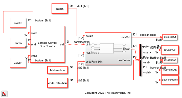
Decode and Recover Message Using CCSDS LDPC Decoder
Decode and recover message from codeword using CCSDS LDPC Decoder.
Ports
Input
Output
Parameters
Algorithms
This figure shows the architecture block diagram of the CCSDS LDPC Decoder block. The Controller block controls the layer and iteration count of the decoding process. The Variable node RAM block stores the variable node (VN) messages, and the Check node RAM block stores the check node (CN) messages. The Functional Unit block calculates the VN messages and CN messages based on the layered belief propagation and either the normalized min-sum approximation algorithm or the min-sum approximation algorithm. The Termination/Parity check status block calculates the parity checks and provides the parity check status after each iteration. For more information about the decoding algorithms, see the following sections.

The latency of the block varies based on the selected Configuration type parameter value, the values of the blkLenIdx and codeRateIdx input ports, and the number of iterations. Because the latency varies, use the nextFrame control signal output port to determine when the block is ready for a new input frame.
The latency of the block is equal to rt + d + L. In this calculation, r is the number of iterations, t is the number of clocks required to decode one iteration, d is the pipeline delay, and L is the length of the input data.
| Configuration Type | Code Rate | Block Length | Number Of Clocks Per Iteration | Pipleline Delay (d) |
|---|---|---|---|---|
| (8160,7136) LDPC | 7/8 | 8160 | 2080 | 27 for scalar and 26 for vector |
| AR4JA LDPC | 1/2 | 2048 | 252 | 10 |
| 8192 | 1240 | |||
| 32768 | 4960 | |||
| 2/3 | 1536 | 316 | ||
| 6144 | 844 | |||
| 24576 | 3376 | |||
| 4/5 | 1280 | 444 | ||
| 5120 | 482 | |||
| 20480 | 2584 |
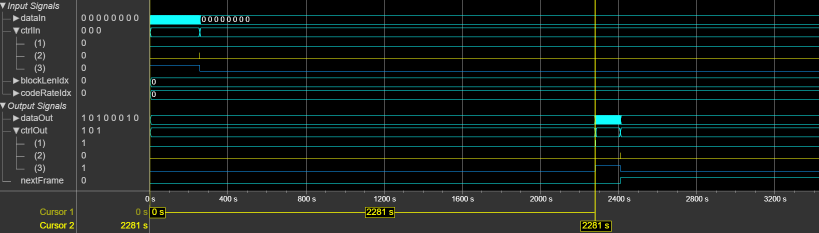
This figure shows a sample output and latency of the CCSDS LDPC Decoder
block for a vector input when you set the Configuration type parameter
to AR4JA LDPC, the Algorithm parameter to
Min-sum, the Decoding termination criteria
parameter to Max, the Number of iterations parameter
to 8, and the codeRateIdx input port value to
0. The latency of the block is 2281 clock cycles.
This section shows the EbNo and BER plots of the block for specified inputs and parameter settings.
This plot shows the performance of the block for a 4 bit QPSK modulated LLR input when
you set the Configuration type parameter to (8160,7136)
LDPC.

This plot shows the performance of the block for a 4 bit QPSK modulated LLR input for a
block length of 1024 with code rates of 1/2, 2/3, and 4/5, respectively, when you set the
Configuration type parameter to AR4JA
LDPC.

This plot shows the performance of the block for a 4 bit QPSK modulated LLR input for a
block length of 4096 with code rates of 1/2, 2/3, and 4/5, respectively, when you set the
Configuration type parameter to AR4JA
LDPC.

This plot shows the performance of the block for a 4 bit QPSK modulated LLR input for a
block length of 16384 with code rates of 1/2, 2/3, and 4/5, respectively, when you set the
Configuration type parameter to AR4JA
LDPC.

References
[1] TM Synchronization and Channel Coding. Recommendation for Space Data System Standards. CCSDS 131.0-B-3. Blue Book. Issue 3. Washington, D.C.: CCSDS, September 2017.
[2] TM Synchronization and Channel Coding. Summary of Concept and Rationale CCSDS 130.1-G-3. Green Book. Issue 3, June 2020.
[3] Stephen B. Wicker. Error Control Systems for Digital Communication and Storage. Prentice Hall, 1995.
[4] Gallager, R. “Low-Density Parity-Check Codes.” IEEE Transactions on Information Theory 8, no. 1 (January 1962): 21–28. https://doi.org/10.1109/TIT.1962.1057683.
[5] Hocevar, D.E. “A Reduced Complexity Decoder Architecture via Layered Decoding of LDPC Codes.” In IEEE Workshop OnSignal Processing Systems, 2004. SIPS 2004., 107–12. Austin, Texas, USA: IEEE, 2004. https://doi.org/10.1109/SIPS.2004.1363033.